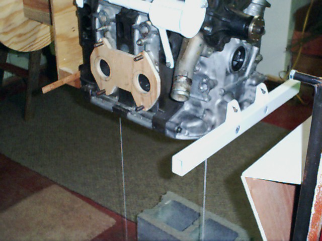
Here is a companion picture to the one you cited. I took both at
Everett's place in Oregon. Note how far out from the side of the engine
the pipes extend. You will not get this into a 20 inch wide cowl as the
engine is 12 inches wide and these pipes stick out another six or seven
inches. You might get this in something like this earlier drawing with
high mounted rubber bushings on Tracy's motor plate. Unfortunately this
early drawing shows an impractical upper mount and there is no obvious
way to brace the motor mount laterally. The rad is too wide as well.
I will correct this and redraw it. A ball jointed A arm might work
but I am very pessimistic about that. I will have to modify this
sketch to see if this can be done. The fact of the matter is the
Mazda rotary engine is designed for a bed mount.

Everett also used a shorter PSRU than Tracy's so it was possible to move
the engine forward.

The huge, almost insurmountable problem with cantilevering the engine from
the back side is getting the loads into the stock RV4 motor mount firewall hard
points and from good brackets on the engine. Just too much in the way.
I am willing to listen to any new ideas on this.

If one is willing to redesign the front fuselage of the RV4 or build a new
rear cover this might be accomplished. The alternator will get in the way
as well as the water pump. Mecanir totally redesigned the accessory section
of the engine to achieve this end.

Paul Lamar

-------------------------------------------------------
Paul,
I am using a front cover from a 1983 12A.  The 'hard points' on this front cover are the primary mount points for the 1979 thru 1985 RX-7's so this front cover should be strong enough for this task.  I am again attaching pictures of my preliminary cantilever mount.  I am in the process of rebuilding this mount again.  The upper right mount is easy, the left upper mount is tough to design.

Thanks,
Ken Powell
Ken Powell
kenpowell@aristotle.net
It is a different set up Ken. The car used the front mount shown in conjunction
with a rubber mount under the transmission. They shared the modest G load.
The front mount took no fore and aft load. Just torque and half the combined
engine and transmission weight roughly.

In this case you are using the front mount in a way it was not designed for.
You are attempting to cantilever 300 pounds off this mount and something else as
yet undefined at the top of the engine. There are no equivalent easy mounting
points on the top of the engine in the vicinity of the water pump.

Cars are not designed to be dropped in from ten feet up. I have seen it happen
however and it is not pretty :-) There is a famous picture of the Nuremberg Ring
winning Chaparral 2F completely airborne over a bump. Most car design loads
are three G's max vertical.

The bottom tube you have shown not only has vertical bending loads but it has
four and aft bending loads due to the fact you are cantilevering the 300# engine.
You would be better off using a three inch by three inch .125 wall square aluminum
tube tig welded to a custom pan. That still leaves the problem of what you
are going to do at the top of the engine.


Paul Lamar

The AirCraft Rotary Engine NewsLetter.              Powered by Linux.
ACRE NL web site.
http://home.earthlink.net/~rotaryeng/            http://www.linux.org