There was some discussion at the Rotary Roundup about intake air flow
velocity. Some think it desirable to keep the air velocity up in the
intake runners. This thinking goes way back in the history of the hot rod
and engine tuning world. Lets look at some of the fundamentals.

Fact one: The amount of air you can get through a pipe increases
with diameter and decreases with the length all other things being the same.
One end of the pipe is always at atmospheric pressure and the
the other end of the pipe is connected to the same suction pump.
Namely an internal combustion engine. The reason this is a fact
is because of air friction inside the pipe that is proportional
to the square of the air velocity.

Fact two: When a pressure pulses travels down a pipe it travels
at the speed of sound and is somewhat a function of the temperature
in the pipe but not the average pressure. The evidence to support
this  is wide spread due to aircraft that have flown
in and around the speed of sound. It also goes way back in history
when the range of a cannon was determined by noting the time difference
between flash and the sound.

Fact three: When pulses of air are forced down a pipe the amount of air
you can get down that pipe depends on its length and the frequency
of the pulses. The interior of the pipe becomes a resonant chamber and the ease
of getting the pulses back and fourth in that pipe depends on supplying
the driving pulses at its resonant frequency. In all resonant structures
the amplitude of the vibration increases when the frequency of the driving
force matches the resonant frequency of the structure. Organ pipes and various
and assorted musical wind instruments are good examples.  In the case of a
four cycle piston engine it is the down stroke of the piston when the intake
valve is open that supplies the pulses.

Fact four: the amount HP one can get out of an internal combustion engine
is determined by the amount or weight  of air that one can get into
the combustion chamber. The ration between the displacement of the
pump and the volume of air ingested into the pump is called the
volumetric efficiency of the intake system

Fact five: Now here is what probably causes the confusion. Not only
is the resonant frequency of the pipe determined by its length
it is also determined by its diameter. This was a little known fact in
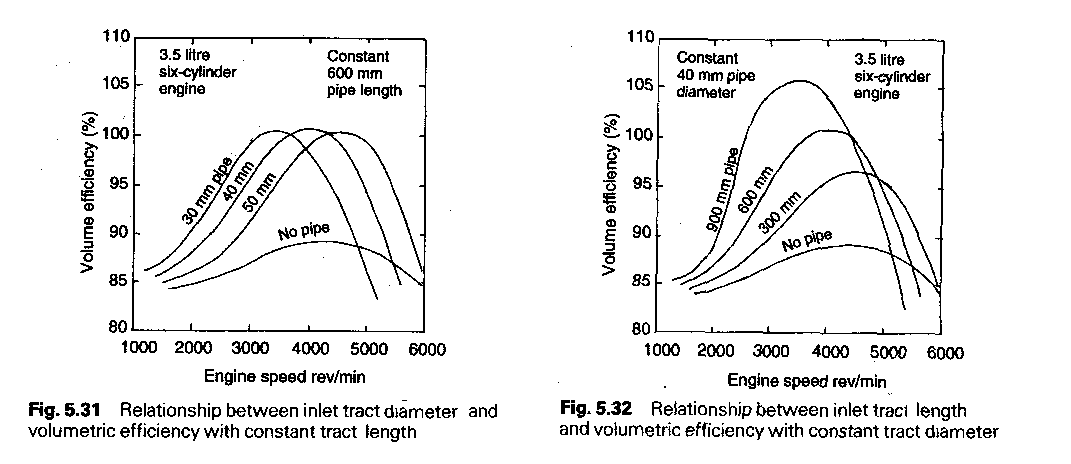
engine tuning circle until recently. Here are two charts from Heinze
Heisler "Advanced Engine Technology" page 246 and 247. Note in the
left chart  that the volumetric efficiency varies with the RPM (he pump
frequency or RPM) AND the DIAMETER of the pipe

This is what led engine tuners to the mistaken conclusion that high
air velocity in the pipe was beneficial to HP.  If the pipe was too
short and the pipe was also too large in diameter the resonant frequency
would be ABOVE the range of engine RPM. Making the pipe smaller in
diameter would show more top end HP by bringing the resonant frequency
down into the range of engine RPM. They mistakenly assumed it was
caused by the higher air velocity in the smaller pipe

If on the other hand they had plenty of top end HP and they saw more torque
or better volumetric efficiency down low they also mistakenly assumed it was
caused by the higher air velocity in the smaller pipe.

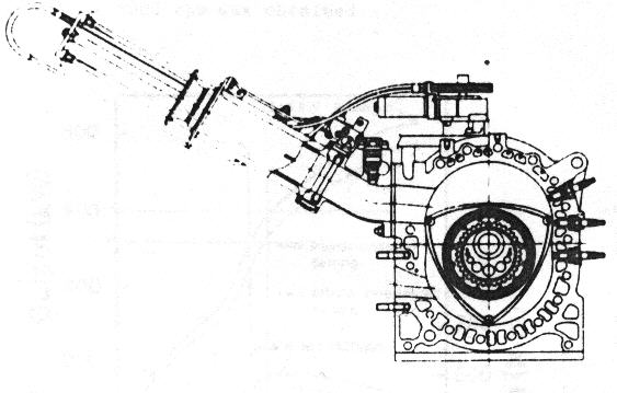
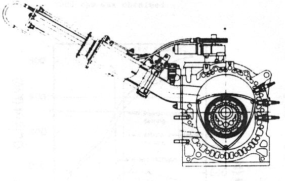
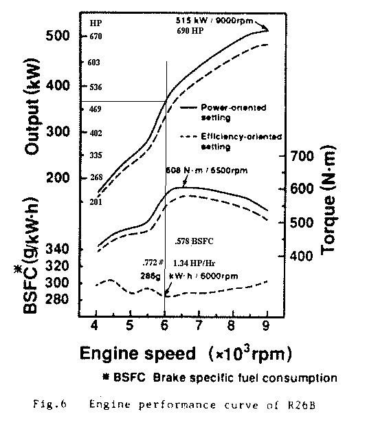
Mazda proved by experiment on the Lemans engine beyond all shadow of a
doubt that what is needed is a long, large diameter, tuned pipe length
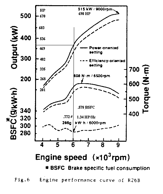
to generate max HP at any RPM. Mazda was able to generate 120 HP
per rotor at only 6000 RPM and volumetric efficiency of over 120%
across a wide RPM range. Here is a drawing of their intake system.

If anybody disagrees with this I would sure like to hear your reasoning.

Paul Lamar

The AirCraft Rotary Engine NewsLetter.              Powered by Linux.
ACRE NL web site.
http://home.earthlink.net/~rotaryeng/            http://www.linux.org