Just because the port at one point is open to two chambers does not
affect
the inertial tuning effect.  The exhaust pulse you bring up does have an
effect (abeit a minor one, as documented in Yamamoto's book) but for the
purposes of this discussion , lets ignore it for the moment.  This
exhaust
tuning effect is a BIG deal in two stroke engines but much less so in
the
rotary.

Lets start with the conditions at BDC.  Air is rushing down the intake
runner at high speed.  The chamber volume starts to get smaller soon
after
this but the air has enough inertia to overcome the rising pressure and
fill
the chamber to a higher pressure. If the intake is properly timed (and
this
is the big goal), the air in the intake runner comes to a complete stop
at
the exact moment the intake port starts to close.  This is many degrees
after BDC.  The pressure is now at its highest point (as shown in your
chart).  At this same instant, the next chamber is opening and the
volume in
it is increasing.  The high pressure in the intake runner is quickly
absorbed by the new intake cycle (which helps fill the next chamber) and
the pressure soon falls to something less than ambient caused by the
expanding chamber and starts the air column accelerating down the intake
port.  Things now progress exactly as they did for the previous cycle.

Just because the port is always open to one chamber or another does not
mean
that airflow does not stop and start.  According to every book on the
subject I've read, the harnessing of energy in the air column inertia is
what intake tuning is all about.

Where's the water leaking out of this theory?  :-)

Tracy Crook
tcrook@rotaryaviation.com
www.rotaryaviation.com
Sounds plausible. Perhaps we can come up with a tiny venturi to measure
air velocity in the intake runner.
No need to get a venturi Paul. Your pressure transducers will work if they
have a short enough response time. Tracy is correct, but there is also a
component of sound in this explanation. The air stopping and starting or
slowing and speeding, whichever you prefer, does create pressure waves. As
that column of air comes to a stop a positive pressure wave is created and
travels up the intake runner in the OPPOSITE direction of the flow. It
emerges from the opening and a subsequent negative pressure wave travels
back down the runner. What you don't want is for this negative wave to
arrive just as the next chamber is starting to fill. It will produce less
flow. What you do want is the negative pressure spike at the INLET of the
runner at the instant the flow is needing to accelerate into the runner.
That is why long runners are better for low speed, and short runners are
better for high speed. Their resonant frequencies are inversely proportional
to length.

The object of keeping the velocity high is that there is more inertia to
work with and the subsequent pressure pulses are stronger. Given the same
airflow, a smaller runner is more efficient than a larger runner because
there are stronger waves to work with. If there were a problem with tuning
the rotary using this method, a large runner could work better, because
there would be relatively weak pulses. I doubt this is the reason for the
large runners on the Le Manns engine, because they are variable length. This
indicates tuning to me, kind of like a trombone :-)Race engines tend to have
massive ports and runners to reduce pumping losses at high rpm, and
subsequent airflow rates. Smaller more efficient runners are more important
when throttle response and low end torque is the name of the game. The
dynamic chamber concept uses these pulses in a different fashion. It
conducts the positive wave from one rotor to the other at the proper times.

There is a book called Scientific Design of Intake and Exhaust Systems in
which most of this stuff is laid out in a fairly easy to understand manner.
It is written by Philip H. Smith and John C. Morrison. They did their work
before computer data acquisition and used Paul's favorite device, the water
manometer to do a lot of testing. It was really quite clever. They used a
bank of manometers attached to pressure taps along the intake and exhaust
tracts of a test engine. They had a valve allowing them to sample a small
increment of time at all the taps. The manometers clearly show the waves
developed in the runners. This is a sound phenomena and can be analyzed as
such. The speed of sound really is relevant.

I myself witnessed this in action. I had a race car that had a four barrel
carburetor on it. If you operated it without the hood and aircleaner you
could see a standing wave or cloud of gasoline droplets hovering above the
inlet at certain rpms. (no it is not smart to operate without an aircleaner
:-) The cloud would appear as if by magic at certain rpms, and vanish
between .25, .5, .75 resonance. Mesmerizing, to watch but dangerous because
it was most pronounced at full throttle and you really needed to be watching
the road!!!

Monty
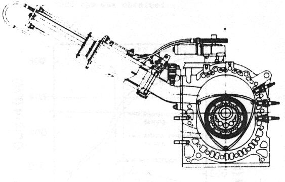
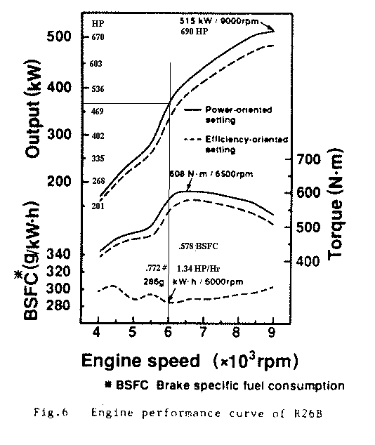
My point on the Lemans engine was if you run it at a constant RPM
the variable runner length would be fixed at that RPM. That means you
could replace the runner with one of fixed length, the same diameter
and get the same HP results. The fact it had variable runner lengths
then becomes irrelevant. That also means we are using runners that are too
small in diameter as the Lemans engine developed 120 HP per rotor or 240 HP
for a two rotor version at only 6000 RPM. The Power Sport engine
with the similar peripheral porting is only generating 210 HP
at 6000 RPM with somewhat smaller diameter (too small) runners.
Do you agree? Does anybody disagree?

Paul Lamar

The AirCraft Rotary Engine NewsLetter.              Powered by Linux.
ACRE NL web site.
http://home.earthlink.net/~rotaryeng/            http://www.linux.org