Al Gietzen wrote:
Paul;

Yes; I downloaded all three charts and did the math.  A typical design
point
for that specific cooler is an oil flow of about 1.5 gpm and air flow of
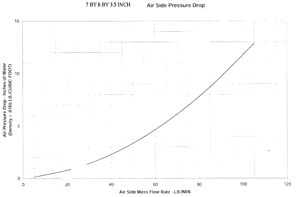
about 20 lbs/min.  That airflow results in a air side pressure drop of
about
4" water; and for that cross-sectional area, an air velocity of 22 mph.
I don't think it is pointless for our readers at all.
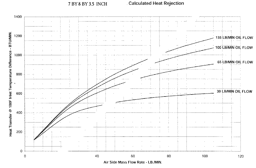
OK here are both the air flow and the heat rejected rate charts.
You choose 20 pounds per minute mass air flow rate.
Entering the calculated heat rejected rate chart
below at about 20 pounds per minute mass airflow gives
only 260 BTU/per minute. Obviously nowhere near enough.
Isn't that exactly the point?  That Stuart-Warner heat exchanger is of no
interest for our applications.

the more important part
of my last message; i.e.;

"I am getting a custom oil cooler from Griffin for my 20B installation.
It
has a core thickness of 3.35", commonly used by NASCAR. The MEASURED air
side pressure drop for the core for the mass flow per unit area that I
need
is 1.48" of H2O. Perfectly acceptable."

And, that with a core size of 5" x 20.4" (x-sectional area of 102 sq in)
get
the
needed heat rejection rate of about 2350 BTU/min for takeoff power on 100
F
day (total air flow 1600 cfm, oil flow 16 gpm, air velocity through the
core
of 26 mph). This is a very compact, effective heat exchanger, and; yes -
it
is nearly 3.5" thick.

Al Gietzen
Since one third of the heat rejection is by the oil and your engine is
roughly 300 HP you will need to reject roughly 100 HP or 74,600 watts
to the oil alone. Waste heat is roughly equal to net HP out.
Converting that to btu/min gives us 4200 BTU/min
I plan for my NA 20B to put out about 260 hp at 6000 rpm at sea level.
Whatever it does beyond that is a bonus.  260 hp is 11,000 Btu/min; and
represents 28% of the fuel burn energy.  Backing up from there, I get a fuel
burn energy of 39,000 Btu/min, and just over 7% of that goes into the oil.
That's about 2800 btu/min.

If I design my fixed inlet to give adequate cooling for this power on 100 F
day, I will be carrying around a lot of drag that I will only rarely need.
I know that my Velocity will take off just fine on 200 hp, so on that rare
day I'll throttle back as I need. Life is full of compromises.  On any
cooler day I can climb faster if I want.   At 200 hp the heat to oil is
about 2150 Btu/min.
The area of your chosen cooler is 100 square inches or five
times larger than this cooler represented by the attached charts.
If you don't mind, will skip the test of that discussion, because there is
no reason to believe that the Stuart-Warner charts are applicable to the
griffin core design.
If you have data for the custom oil cooler from Griffin
that differs greatly from the charts in the SW pdf file please by
all means share it with us.
Unfortunately I don't have the performance curves for their core.  What I
have is what the engineer says is actual performance their core design (the
3.35" thick core) for a cooler with 105 sq. in. of area in a "very similar"
configuration.
Oil inlet temp - 220 F [120 degree difference when the outside air is 100 F]
Air flow - 1575 CFM [120 pounds of air per minute.]
Air inlet temp - 100F
Oil flow - 18 gpm [at 7 pounds per gallon ..2.6 pounds per minute]
Oil outlet temp - 185 F
Air side pressure drop - 1.48" H2O [22 MPH]
Oil side press drop - 26 psi
If I did the math right, that oil Delta T is equivalent to 2380 Btu/min heat
rejection.
Close enough for me. (my design point is 16 gpm oil, 1600 cfm air).  Until I
have the oil cooler and can do some measurements on it, I'll have to accept
their data.

BTW; this is a slight improvement in performance from what they came up with
for me about a year and a half ago.  At that time they were not able to
build my cooler and have it survive cycling to 125 psi.  They have improved
their brazing process, and apparently changed their tube design (more
internal turbulators) to withstand higher pressures.  The oil side pressure
drop is about three times what they gave me back then.

Al
I converted some of Al's numbers to the same units used in these 7x8x3.5
inch cooler charts for direct comparison purposes.

The big difference over these charts is the mass airflow is very low
by comparison in the Griffin coolers at 1.5 inches of H2O judging by these charts.
I find their numbers extremely hard to believe as there are only minor
difference from one heat exchanger design to another.
The cooler represented by these charts requires substantial air
pressure differences to flow the required mass of air.
I would be much more inclined to believe their numbers if their
cooler was a half inch thick.

On the air side the CFM (pounds of air per minute) is a function
of three variables. Namely the pressure drop across the core, the
area of the core and the thickness. It is possible to get the
mass airflow up with low air pressure and thick cores by going to a
much larger area core. Given a big enough thick cooler it will work.

On the heat side the heat dissipation at a given
mass flow is mainly a function of the volume  (H x W x T) of the core.
Thick cores being less efficient for a given volume due to the
first half doing three quarters of the work rule. This is
true because the air heats up as it travels through
the thick core and therefore the temp difference between air and
oil is reduced.  So too is the rate of heat transfer.

In other words thick cores take a double efficiency hit.

Paul Lamar

The AirCraft Rotary Engine NewsLetter.              Powered by Linux.
ACRE NL web site.
http://home.earthlink.net/~rotaryeng/            http://www.linux.org