This appears to be a forged crank but it is lacking
the large radii in the journal area necessary to
lower the stress concentrations and make the crank last
the requisite number of hours for aircraft use. All aircraft
cranks that I have seen have large radii in this area that is
known to reduce stress concentrations.
 I agree that the large radii will reduce stress concentractions. But I was
lead to believe that their primary function was to take the thrust loads.
This is one reason they're not on automotive cranks and are present on all
direct drive aircraft piston engines. Does this make sense from an
engineering standpoint or is it just an over simplification from A&P school?

James Phillips
I think somebody mis informed you in A & P school. There are separate
plane thrust bearings in all aircraft engines. There is a chart in Taylor
on this subject of crank radii verses stress concentration and I will
scan it in and up load it as soon as Robin stops using her computer.
In the mean time here is another interesting chart from the Sky Ranch
Engineering Manual I think.

Paul Lamar
Paul is, as usual, correct.  The purpose of the fillet radius on a transition
in size of a shaft is to minimize the stress concentration at the inside corner.
Bigger radius, lower stress concentration.

By the way, Paul, your broken crank pic is a VW.   I had one do that exact
thing on me in a car.  Started thumping something fierce, but was smooth
at idle.  Drove it 35 miles home at 55 mph or so after a brief roadside
troubleshooting effort that found nothing.  When I grabbed the crank
pulley at home I found I had about 1/4" fore-aft play! I thought the flywheel
was coming loose, so pulled the engine.  Found the flywheel tight and the
rear pulley and flywheel moving 1/4" independently.  Broken crank. The
mains were holding the pieces in alignment enough to get me home.

Bill Freeman
Long EZ builder & pilot
BSME, MSME
EAA Technical Counselor
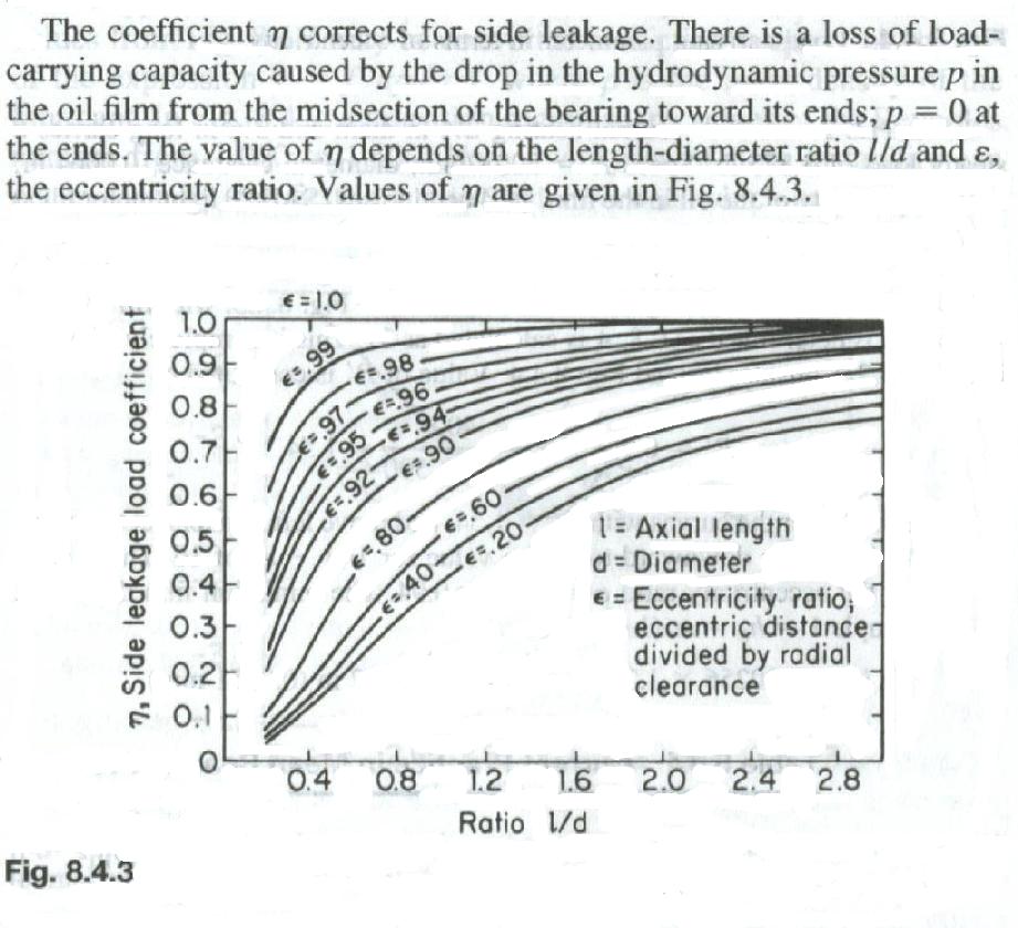
Here is something else to think about. This is the ratio of the width
of a journal bearing to its diameter. It seems on the face of it that
one can reduce the stress concentrations in a crankshaft by merely
making the main and rod journals larger in diameter and there
by increase the overlap. This works to a certain extent but one must
be careful to not make the bearing so large in diameter that
it losses dynamic oil pressure along its edges. Here is a chart that
explores that relationship. The eccentricity ratio is merely the clearance
of the bearing relative to its diameter.

Again it appears that the crankshaft must be longer to take advantages
of the larger diameter main and rod journals. This is probably unacceptable
in a car engine design. More acceptable in an air-cooled four cylinder
horizontal opposed air craft engine due to more space between the cylinders.
Longer cranks have lower torsional frequencies all other things
being equal. Fortunately all other things are not equal. To counter
this larger journals reduce the frequency.

The other drawback to larger main and rod journal diameters is it
increase the friction in the engine and raises the fuel consumption
slightly. The weight increase can be overcome with larger bores in
the journals.

As you have probably guessed by now the current air cooled air craft
piston engine is pretty well optimized consistent with the materials
available. The piston engine is pretty well up against a brick wall
design wise. We have just begun with the wankel rotary and already it is
far superior to the piston engine structurally speaking.

This chart is from Marks Mech. Eng. Handbook.

Paul Lamar

The AirCraft Rotary Engine NewsLetter.              Powered by Linux.
ACRE NL web site.
http://home.earthlink.net/~rotaryeng/            http://www.linux.org