daniel gagnon wrote:
Is it normal we don't see a hole in the flange. Where
the fuel pass in that.
Just kidding...

I propose the plastic just to making some static test
on a bench, to prepare the best sand mold we can have
after for aluminum partssss.

Daniel
If you can do that Daniel we can send you the file. Which one do you need?

Paul Lamar
Do you have an accurate CAD drawing of the lower intake manifold surface,
showing the bolt patterns and the location of the intake ports.  I'm looking
at using an aluminum plate that transitions to fiberglass intake tubes.  A
friend of mine will mill out the plate. The numeric equipment that he uses
can wire cut a smooth transition between the oval pattern to the round
pattern.  My goal is to coil the fiberglass tubes on the side of the engine
so that I can mount the engine as high as possible.  We will mill the outer
injector ports into the aluminum plate so that the fuel will not pass
through the fiberglass section.
I'm experimenting with different forms for laying up the fiberglass tubes.
So far, the foam insulation that you use to cover your hot water pipes
proves most promising.  I will run a plastic tube through it so the foam
holds its shape when formed into a coil.  I bought some long 'tube' baloons
that I will try to pull over the foam (inflating the baloon via the plastic
tube) while drawing it over the foam.  That will give me a smooth surface to
lay up the fiberglass and should release after the foam is dissolved and the
plastic tube removed.

Del Johnson
I have a drawing but I can not guarantee it is correct.
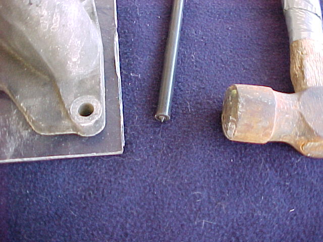
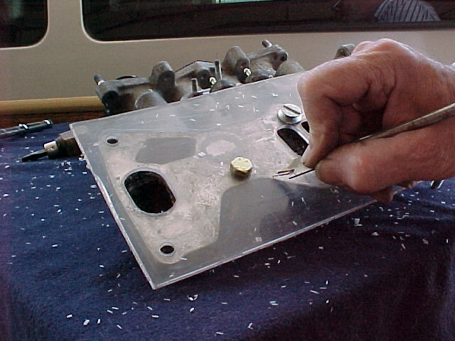
I suggest you make a pattern using 1/8 thick Lexan sheet and transfer punches.

Paul Lamar

The AirCraft Rotary Engine NewsLetter.              Powered by Linux.
ACRE NL web site.
http://home.earthlink.net/~rotaryeng/            http://www.linux.org