Not Mach 1 according to Taylor it is Mach 0.45
Skin friction losses in the pipe well below Mach 0.45 are in addition to
the Mach number effect. Large pipe.. lower velocity.. skin friction is
proportional to velocity squared... lower drag.

I think a good analogy is a woofer speaker.
The larger the cone the more efficient the speaker. It couples
better to the air around it. It is related to impedance matching.

It is easier to start a large mass of air moving with a large
hole and large piston. When the piston or rotor attempts
to get as much mass of air as possible moving it is better to do it
with a large hole and a large pipe.

Another analogy is the large rotor diameter on a helicopter. Max
thrust at zero vertical velocity.

The Mazda Lemans engine is simple and absolute proof of this concept.
When somebody builds a rotary engine that generates more power
than the Mazda Lemans engine at the same RPM with a smaller pipe
and smaller port I will believe other wise. 240 HP for a two rotor
at 6000 RPM is a worlds record so far for NA rotary engines.
Nobody else comes close. The VE is well above 100% over a wide RPM
range. Peak torque or max Ve occurs at 6500 RPM with a very flat
but slightly decreasing VE and torque above that up to 9000 RPM.

Almost a straight line between 620 Nm at 6500 to 580 Nm at 9000 RPM.
The slight decrease in VE and torque I believe is caused by the increased
pipe skin friction due to increased air velocity (~V^2) out weighing the
decreasing length of the tuned pipe.

If it were not for keeping the apex seals in the rotor slots I believe
the rotary would generate even more HP per rotor at the same RPM
as the Lemans engine with even larger pipes and wider intake ports.

SAE Mazda paper 920309.

Paul Lamar
Paul,

The Lemans engine is indeed a work of art. The Port is large by our
standards. This does not mean that it is gargantuan. It is simply sized for
high rpm operation.
Wait a minute! It has the worlds HP record for 6000 RPM. That is not
high RPM for a rotary. Nobody but nobody has got more power at 6000
RPM!!!! At 9000 RPM the Lemans engine has more power per rotor (172)
than even the 290 HP RX8 prototype which had 145 HP per rotor at 9500
RPM. Why? Lower air velocities in the runners!
One of the things you tend to shoot for in runner sizing
is not having an area smaller than the port or valve aperture. This is
complicated in valved conventional engines by the fact that there is a valve
stem and several turns and transitions in the runner. This is where airflow
Voodoo comes into play. On the Lemans engine It is fairly straight forward.
It looks to me like the runners are the same area as the port, as it should
be. They are also the most efficient shape, a circle.
The port it self is rectangular.
People looking for
some type of secret magical shape for a runner should just look at a circle.
A tube has the least amount of wall area per flow area of any shape,
therefore less frictional loss. This is true when the airflow is straight.
When you are accelerating the flow (ie changing its direction) then you can
get non uniform flow fields and different port shapes can work better, like
the D port etc. The Lemans engine also has variable length runners to take
advantage of sonic tuning. They also have a nice bell shaped inlet, best for
flow losses, and sonic tuning. The runners are straight. They did everything
right. You will note that they did NOT make the runners much larger than the
port.
I agree with this. But the port is limited in width to keep the apex seals in
the slots. It is limited in height for valve timing purposes.
I suspect it is probably possible to get even better
breathing if both side ports and a peripheral ports are used
together with one large runner for each rotor and with even lower
main runner air velocities than the Lemans engine.
It looks kind of like they did in the cross section view, but the port
is more oval shaped and I bet the cross sectional areas are not far from
equal. They did make a larger port than the typical rotary, which flows
better and makes better peak HP numbers. With fuel injection, you don't have
to worry about the fuel suspension problem like you do with a carb, so this
works well. However, I bet the throttle response below 3000 rpm sucks!
As I said before we don't care about that. It has that has no consequences for
an aircraft engine. I will not argue that point. For all I know or care there
is an optimum air velocity for good throttle response over a wide
RPM range. In fact Ken Powell is trying to solve that problem as
we speak. I even fabricated some parts to help him in his quest.
The
thing probably idles at a ridiculously high rpm, and not all that well. It
is a high strung race engine. In a fast, slick airplane with a fixed pitch
prop, a peaky high strung engine that idles at a high rpm is not the best
thing. Now if you put a variable pitch prop on the thing and control thrust
that way, while keeping the revs up, you may have something.
It idles fine. Albeit at 2000 RPM.  They had it here in So Cal at the Seven Stock
meeting a few moths ago and I heard it run. Heck I have a street motorcycle that idles
at 2000 RPM. Ken's engine with variable port timing will idle even better
and show near the same HP per rotor at the same RPMs.
I still say your chart of VE vs Mach number makes Tracy's argument and mine
as well. There is a definite optimum value. It is worse both above and below
that point. But strictly speaking, all of those engines were carbureted. So
you would have to do the same test with a fuel injected engine. I bet you
would see the same thing, maybe shifted towards the lower mach numbers
somewhat.
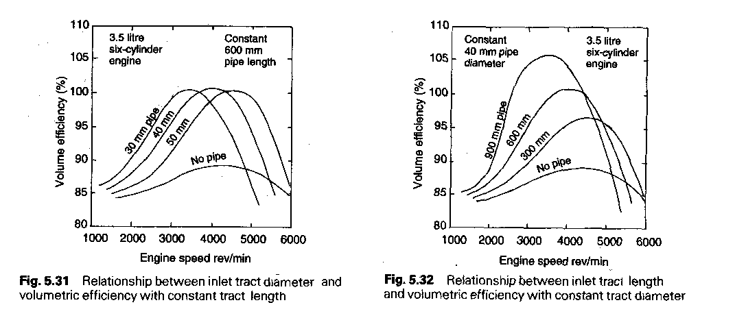
I strongly disagree with your interpretation of that chart. So does Taylor.
Here is a modern chart from Heinz Heisler's book  that also shows a drop off in
VE as runner air velocities increase. Note that despite more skin
friction drag in the pipes as the RPM and air flow are increasing
(in the left most chart) VE is remaining near constant as pipe sizes
are also increasing. HP of course is rapidly rising with the RPM
and additional air flow.

In the right had chart; note also that as air velocities
increase, despite the shorter pipes with less skin area, VE is
rapidly decreasing with increased runner air velocities.
If both pipe diameter and pipe length where  both increased
the VE would not drop off or drop off at a far lower rate.
More like the rate of the VE drop off in the Lemans rotary engine.
Whomever made this chart did not complete the experiment.
Many more charts should have been made with larger and larger runners
over a range of pipe lengths. For some strange reason he limited
himself to the 40 mm pipe dia. case when the 50 mm pipe dia. case
resulted in more power at higher RPMs. Probably looking for low
down HP and torque.

The bottom line message is: Make the runner dia. and port area
as large as possible and tune the length for max  take off HP at the peak
prop RPM. The engine RPM at this point will vary according to
the PSRU ratio used. For a rotary something around 3:1 PSRU ratio looks
about right.

More evidence. Runner sizes are increasing in all types of piston
engines as more manufactures go to two intake valves per cylinder
which gives more port area.
I have to go tear down a chimney now {8-0

Monty
So far you guys have shown me no data to support your contentions.
I guess I am going to have to scan yet many more graphs from Taylor to
convince you guys. It would be better if Tracy took some of that $500
he has and bought the two volume set of Taylor's bible of engine design
books. Would save me a lot of work :-)> When I would go up to see Everett
Hatch years ago he would carry his Taylor around with him
where ever he went. We would go out to lunch and he would quote
various passages. I miss the guy.

Paul Lamar

The AirCraft Rotary Engine NewsLetter.              Powered by Linux.
ACRE NL web site.
http://home.earthlink.net/~rotaryeng/            http://www.linux.org