Static's professor hat going on....Brian, you did not make a balsa model
 of the rear mount did you? If you do and if you put a side load on
 either rear triangle you will see the problem. As far as the structure
 goes you cannot assume the rubber mounts will take side load. The mount
 must be laterally stiff on its own. Act like the rubber mount is not
 there. In that case you need some lateral bracing for both rear mounts.
 An X would be nice made from 1/2 inch dia tubing.

 Having said that... Now I will tell you there is near zero load
 on the rear mounts. The right side aluminum angle bracket is
 100 times too strong and too heavy. The front mounts are
 going to take 95% of the load as they are located under
 the CG of engine/gearbox/prop/starter combination.

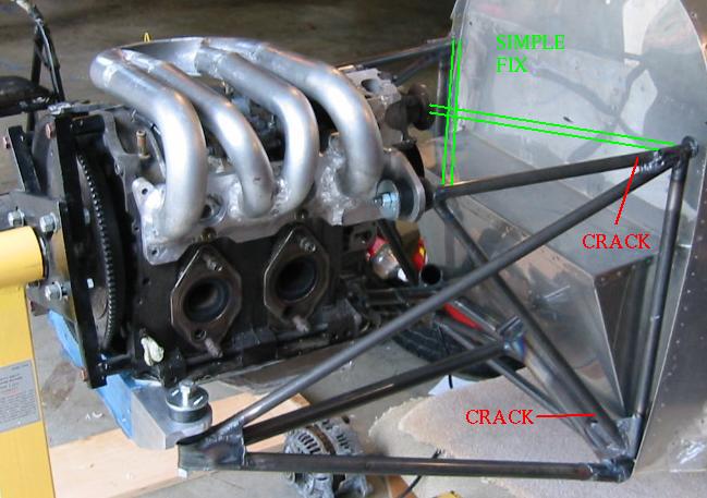
 Here is a picture of your mount and the Questair Venture rear mount
 for a Continental TIO-550. The Continental is supported at the
 front in a near identical manner to your front mount.

 Here also is a drawing of my version of the Questair rear mount
 for my Kis Cruiser.

 Paul Lamar
Paul,
If your Questair type mount (totally limp in left-right movement) works, why
does brians need to be triangulated?  What am I missing here?  My
understanding was that the Q type mount only supports the up-down movement,
and works because the load is low.  But it looks like it will not have any
side to side rigidity.

What is the size of your under mount rad?

Bill Schertz
KIS Cruiser #4045
Very good question Bill. Ironically it is because the front mounts do allow the
engine to move around. What happens is a small lateral bending load
is put into the two rear mount triangles through the rubber
bushings that may cause then to fatigue and crack at the points
shown in this picture. The magnitude of these loads is highly
dependent on the stiffness of all the rubber bushings involved
and it takes a computer to estimate them. It is best to be safe and
not allow this to happen.

http://www.ljkamm.com/mincd.htm

Principles of Minimum Constraint Design.

Every rigid body has six degrees (or axes) of freedom: x, y, z, roll, pitch, and yaw. Six properly selected points of constraint prevent any motion and do so
with no bending stresses imposed on the body. Five points leave one axis free to move, and so on. This is Minimum Constraint Design.

Since a pure point of constraint would impose high local stresses, small areas of constraint are often used. This is Semi-Minimum Constraint Design.

With Minimum Constraint Design external loads may impose large stresses on the body and on the constraints, so additional constraints may be desirable.
This is Redundant Constraint Design. (A ball bearing is an example of successful RedCD.)

DESIGNING COST-EFFICIENT MECHANISMS is a study in depth of these matters and presents extensive guidance in their use in design. It gives examples of each idea.

Questions? Telephone me at 619-224-3494 or e-mail ljkamm@ljkamm.com. No charge!

Lawrence Kamm, Consulting Engineer

For more on this subject look up redundant constraints in the
field of mechanical engineering.

Paul Lamar

The AirCraft Rotary Engine NewsLetter.              Powered by Linux.
ACRE NL web site.
http://home.earthlink.net/~rotaryeng/            http://www.linux.org