Al Gietzen wrote:
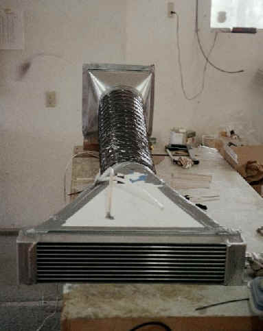
Attached is a photo of the flow test rig for my Griffin oil cooler.  As was
the case with the radiator flow test described here a week or so ago; the
output from the blower was not sufficient to get to the design point of 1600
cfm.  The flow velocity through the core was varied by progressively
blocking off the face area of the cooler core from both ends, and measuring
the exit velocity at the center of the face of the core with the Radio Shack
anemometer.  The max pressure the blower would generate was 0.56 " h20;
which is equivalent to 1020 cfm (core x-section area is 96.5 sq. In.); so in
order to test these things properly we need something better than heating/AC
blowers.

The 5 data points measured from 400 cfm to 1020 cfm show the pressure drop
varying as some sort of quadratic, (definitely not as the cube as I had
assumed in my radiator flow test).  I then used Excel to do a regression
analysis fit of the form a + bx + cx2 (which gave a very good correlation)
so I could extrapolate to the 1600 cfm design point.

I thought that Griffin's value of 1.4 in h20 air side drop at 1600 cfm
(average velocity 40 fps) for this core might be very optimistic, but my
extrapolation gives 1.2 in.  Extrapolating that far from the last measured
data may be a little off, but the values ar far from being a problem.

The data is tabulated and charted on the attached Excel spreadsheet (for
those of you who don't hate Microsoft too much have XL).  A few data points
are:
15 fps       0.25" h20   613 cfm
22             0.44           890
28             0.66           1125
34             0.92           1366
40             1.22           1608

It shows that a core thickness of 3.37" with this tube and fin arrangement
(14 fins/inch) is just fine if you have an effective scoop and diffuser to
slow down the air.  In my installation it will have a diffuser ratio (inlet
to face area) of  about 1:4.

 It also tells me that the pressure drop across my coolant radiator at the
design point is much less than the 3" h20 I had reported, since the "cube"
variation of pressure drop with flow velocity was way off.  The one point I
had measured on that core falls quite close to this curve, and suggests
about 1.4" h20 at the design point. (2 ½ core, 16 louvered fins/in).

It also suggests that the pressure differential across the wing in the wing
root installation will provide very good flow.
The AirCraft Rotary Engine NewsLetter.              Powered by Linux.
ACRE NL web site.
http://home.earthlink.net/~rotaryeng/            http://www.linux.org