Jerry Hey wrote:
Paul,   On one drawing of the PRSU adaptor plate the ribs between the
pockets are 0 .5" wide.  On the other  drawing they are 1.0" wide.

The  inner bolt circle on one drawing shows a bolt lined up on two
o'clock rib.   On the other drawing this is rotated clockwise and a
bolt
is lined up on the three o'clock rib.
The rib positions are not important.
It is not the ribs I am concerned with but the bolt hole pattern.  I
have not seen Tracy's drive to examine it.  Does it have a  fixed
position, probably with the drain at the bottom?    If so, then we need
to locate  the bolt holes to maintain the horizontal axis of the motor
mount plate.
Use the bolt hole positions from the drawing. Check with the back
of your engine if in doubt. The rotation of the smaller holes to mount
Tracy's psru are not that important.
Can we assume that the starter hole and attaching bolts will be the
same
in every case?  If so we need the numbers or if not, then what do you
suggest we do?    We could punch a small hole to center the starter
There are several different starters. If you put in the large starter
pilot hole
a person could drill his own starter bolt holes depending on which
starter he wanted to use. I think they all have the same pilot hole
diameter.
O.K.
Are the outer bolts counterbored?    I don't understand the comment the
"wrap the spool  in 1/8" aluminum."   Also, don't understand the
comment
"Y Drill Hole."
Two of the aluminum spools are counter bored for the hollow dowel pins
used in the Mazda rear end housing. The 3/16 aluminum wrap is used
instead of Tracy 1/2 inch plate spacers which are quite heavy and
crude looking :-)>

The 3-1/8" wide 3/16" thick aluminum sheet wrapped around the outside of
the spacers takes all the sheer loads due to engine torque. You could
use
steel spacer and .040 steel sheet in effect fabricating a bell housing
of
sorts that encloses the flywheel/ring gear. Again this is mainly a
cosmetic
issue.
Sorry to be so dense but I am not getting the picture.   Can you send a
picture?
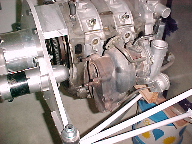
No pictures but here is a picture of Tracy's spacer blocks.
Visualize a cylinder made from 3/16 thick aluminum sheet 12 inches in
diameter 3-1/8 long with one inch dia. aluminum tubes every 45 degrees
more or less forming a bell housing around the ring gear between the
block and the motor plate.
  We will be ready to run a test of the CNC  program once we
understand
these issues.   After a simulation run,  we will cut a sample out of
butter board which I will bring to Santa Paula.

Also,  what level of finish would you like to see.    The finer the
finish,  the more it will cost but I think some additional expense
for a
beautiful part is o.k.                 Jerry
We had a big discussion about the stiffness of the plate so I made
the ribs wider to make Tracy feel better. The pockets are strictly
cosmetic as there is little weight saving. We would be lucky to get
two pounds out of it. On the other hand it will look trick
and much more professional and therefore will sell more rotary
engines :-)>
The finish is up to you but that too is not important.

We don't want our engines to look like where they came from.....mainly
the junk yard :-)> We want them to look high tech and expensive :-)>

Paul Lamar
Thanks for the quick response. Jerry
The AirCraft Rotary Engine NewsLetter.              Powered by Linux.
ACRE NL web site.
http://home.earthlink.net/~rotaryeng/            http://www.linux.org