Tom, thank you for all the updates. We hope the enthusiasm will yield a lower
price.
I guess the scheme from the sockets will be a 1" long stub welded to a 90 deg
elbow to a straight tube over the top to a 45 deg elbow ( with injector
sockets welded on ) to a 1" stub that then goes into a composite plenum.
We are looking at designing a composite plenum with the appropriate
bell-mouth intersection of the tubes into the plenum and the 3" connection to
the throttle body being centered and dropping vertically from the middle of
the plenum. Our intercooler will be somewhere down under.
It seems there is now a market for the tubular pieces, perhaps with the
longer tube in the middle being joined with a piece of flex tubing giving
some adjustability between the two elbows depending on people's plenum
arrangements.
Anyone out there doing picture perfect tubing welds?
...Chrissi
Due to the radius of the bends Chrissi the straight sections that plugs into
the manifold will be approximately 1/4 inch long. As soon as I get the manifold
I will know for sure and I will give you a drawing on the bends to be used.
Bends come with various lengths of straight section so check out the
RB Wagner catalog.

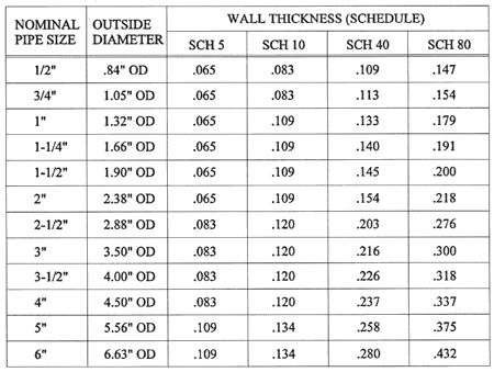
Also this is pipe and not tubing. The sizes and wall thickness are
different. Pipe is thicker wall so it allows a smaller bend radii which
is what we need to keep the runners down on top of the rotor housings.
This is necessary to clear a lot of cowls in various airplanes.

We are using 1-1/2 Sched 5  and 1-1/4 Sched 5 pipe. See the actual dimensions
below. Both have .065 wall which makes welding a bit easier.
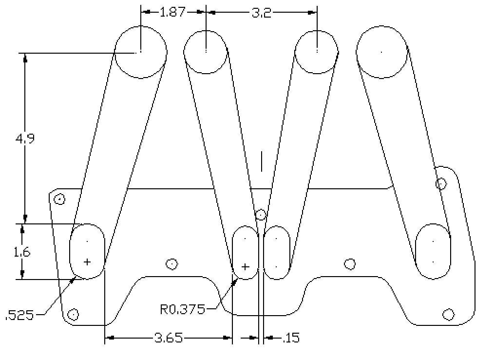
The drawing shows what we are shooting for more or less.

Paul Lamar

The AirCraft Rotary Engine NewsLetter.              Powered by Linux.
ACRE NL web site.
http://home.earthlink.net/~rotaryeng/            http://www.linux.org