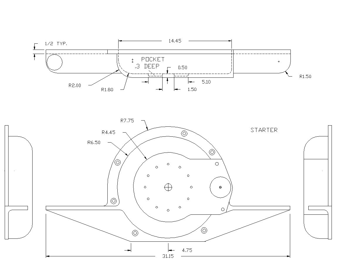
OK Jerry and Blake here is the plate dimensions from the horses
mouth. Tracy kindly printed the drawing and I scanned it in at 500 pixels
to the inch when I got home. You will need a good viewer or printer to
read the fine print.
If this is still not good enough I can scan it in at 600 or more pixels to
the inch.

Just to set the record straight it is better to mount the engine using
this plate as the motor mounts ultimately react the 400 ft pound avg. prop
torque pulses.
The engine puts out two hundred foot pounds avg. and the gear box doubles
it.
If the motor mounts are fastened directly to the engine they see the
prop torque pulses through Tracy's spacers and long bolts increasing the
deflections.
The only case where this is not true is if you drop it in on a six
G crash and then the spacers see less vertical shear load but not much.
That is probably a once in a life time landing and then the
load is only for a fraction of a second. The torque pulses on the
other hand are day in and day out.

BTW I highly recommend estimating the weight of your motor mount design.
Aluminum weighs .1 pounds per cubic inch and steel .3 pounds per cubic
inch.
Four inch longer .049 wall 3/4 diameter tubes weigh very little.

A 3/16 thick steel oil pan sandwich plate 16 inches by 16 inches on the
other hand
would weigh 14.3 pounds with no holes. A 3/4 inch diameter .049 wall tube
4 inches long would weigh .14 pound. Six of those would weigh .84 pounds.

Does everybody understand this? Am I being clear?

Paul Lamar
Uh... no.  The drawing came through fine.  It's the statement that the gear
box doubles the torque that has me confused.  The torque pulses from the
engine should be doubled getting transmitted to the prop (T = Hp / w ;
Horsepower is constant, but the speed at the prop is ~half, so the torque
gets doubled).  The engine/PSRU react to the prop torque and send that back
to the airframe via the engine mount.... OK, I get it now.  But location of
the mount shouldn't have any effect on the torque "felt" by the airframe due
to the running torque of the prop.
Yes that is true. What matters is how the prop torque gets to the mount.
Does it go through the spacers or not? If the mounts are on the motor
plate it does not go through the spacer and they are only subject to engine
torque. Conversely if the mounts are on the engine the much higher prop
torque goes through the spacers.
Seems to me that the engine/PSRU should connect to the motor mount as close
to the assembly's CG as possible.  Probably somewhere near the rear rotor
housing.
True Tom and this is a compromise. A bell housing casting would move the mounts back
towards the engine/prop/PSRU/etc. CG several inches. The rear (front in a pusher)
mount takes up the slack however which amounts to only about 50 pounds or so.
Here is my preliminary cast bell housing design.
FWIW:  The stock engine mount locations for the 20B straddle the rear rotor
housing (Bolt to the rear and intermediate housings).  This looks almost
ideal for a mount attachment point for that engine.  Will probably need an
additional stabilizing mount point near the front (now rear) end though.
Not sure just how to work in the intake/exhaust plumbing with this
arrangement though.

Tom Kendall
This should read:

"The only case where this is not true is if you drop it in on a six
G crash and then the spacers see >more< vertical shear load but not much."

Paul Lamar

The AirCraft Rotary Engine NewsLetter.              Powered by Linux.
ACRE NL web site. Copyright 1998-2002 All world wide rights reserved.
http://home.earthlink.net/~rotaryeng/            http://www.linux.org