I was organizing some files and I ran across these
pics. This motor mount is in dire need of fixing.
It is dangerous they way it is. If somebody recognizes
these pics please prevail upon this person to fix this motor
mount. The red lines indicate the required missing tubes.

A big problem when installing any auto engine is engineering
The motor mount. With a certified engine it is no problem.
Just copy a Cessna or Piper.

If you are not an experienced structural engineer
it is easy to screw up. I highly recommend making a 1/4 scale
balsa model using 3/16 square sticks and check the stiffness.
You will rapidly discover problems if it is not right.

Paul Lamar
Perry Casson wrote:
Hi Paul,

I'm the owner of this mount,  and when I posted the pics last spings you
pointed out your discomfort with it back then.
Anyway, for the extra 1/3 lb it cost me I added one on the right side just
so eveyone could be happy and I'll see if a left tube is possible now while
I'm fitting the header pipes.

Perry Casson
Building exhaust, a bit of plumbing and then ready to fire....

Here's our exchange from last march: [see below]
Thanks for identifying those pictures Perry. A general rule of thumb
is every rubber motor mount needs three tubes. There are exceptions
to this rule. If there is a single stabilizing link tube such as found
in the Questair Venture design it must have either a ball joint or
a rubber bushing on both ends.

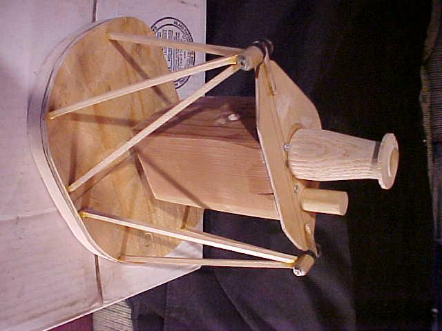
For the new guys here is a pic of my 1/4 scale balsa model.
The aft vertical stabilizing link is not installed or shown.

Paul Lamar


Old message:
--------------------------------------------------------------------
Perry, like I told Mike you need some up and down bracing on
the rear mounts.
The front mount configuration is fine if not a bit space
consuming vis a vis
the rad under the engine trick and the cross tube. A lot like
my C182 BTW.

More about this (and your pictures) when I get a bit more time.

Paul Lamar
Perry Casson wrote:
Hi Paul,

Thanks for the comments, I did look a couple ways to form a complete
triangle on the rear mounts.  It would be tight but possible to run a 3rd
tube from the rear to front cups but that would eliminate the possibility
of
a side mounted alternator which I think I'll need.  When I looked at the
loads on the rear two mounts (~ 15 lbs at 1G) and considered that several
mounts (Lancair 235 or see Bingelis's FWF book page 78) that actually only
have one tube running to the upper points I was pretty sure 2 short large
tubes would be overkill.  Not too late to reconsider though...

Perry
There is a more subtle thing going on here and it has to due with the
concept of redundant constraints. The rear mount sees torsion
due to the four mounts. The amount of torsion it sees depends on
the distance between
all of the mounts and their stiffness. You would be better off with just
one rear mount that was properly triangulated. My choice would be the
right rear looking at it from the pilots view. Take the other one
on the water pump off and save the weight.

Paul Lamar
----------------------------------------------------------------------------
End of old message.


The AirCraft Rotary Engine NewsLetter.              Powered by Linux.
ACRE NL web site. Copyright 1998-2002 All world wide rights reserved.
http://home.earthlink.net/~rotaryeng/            http://www.linux.org