> > John Gibbons wrote:
 > >  >
 > >  > Okay, am I just dim or what?  These measures are quite precise
(1
> > > degree ), so when you have your rotor housing on the bench,
how do
find
 > > TDC
 > >  > within 1 degree ? When you answer I'm sure I'll say yeah, duh.
> > Check Paul Yaw's web site. He has some pictures on there on how
to
> > do it within one degree. He uses a degree wheel on the nose of
the
 > >  e-shaft.  http://personal.riverusers.com/~yawpower/
 > >
 > >  Paul Lamar
> It isn't quite that easy. If you have a fixture that holds the
tip
of
the
 > dial indicator at a precise location that replicates the exact
center of
the
 > rotor housing it is easy.

 > Also if you get that far, you actually rock the shaft back and
forth
over
TDC
 > to the same place on the dial indicator. Say .100". Then move the
degree
> wheel to put the TDC mark on the wheel to null between these two
locations.
> This because the bearing surface is so large in diameter that the
dwell
> around TDC will give a wide range of locations that can pass as
TDC. So
turn
 > the assembly until the indicator moves .100" one way and make a
mark on
the
 > degree wheel under your new pointer.

 >  Then move the assembly the other way, back passed zero (suspected
location
 > of TDC) until you see .100" again and make another mark on the
degree
wheel.
 > Now TDC is exactly half way between these two marks. During this
measuring
> trauma, just pretend that the degree wheel is blank. It has no
degree
marks
 > at all. In fact, you could use a blank disc for this. Finding half
way
> between the marks is easy with a child's compass. If you use a
degree
wheel
 > to find TDC you can just count off the number of degrees between
the two
> marks. Once you have the TDC mark on the degree wheel or a blank
disc,
you
 > rotate the crank to put the TDC mark under the new sheet metal
pointer
you
> made. Now loosen the degree wheel to crank connection, and rotate
the
degree
 > wheel until the TDC mark on the degree wheel is under the pointer.
Now
mark
 > the pulley under the pointer to record TDC. Tighten the degree
wheel to
crank
 > connection. Now turn the engine backwards until 24 degrees (or
whatever
you
 > want to use for spark lead) is under the pointer and mark the
pulley
again
> with a different color paint. That mark will be you max spark
advance.
Piece
 > of cake.


 >  Also the stock pointer (if there is one) is very hard to use. One
must
sight
 > along one of the water pump studs across the pointer to get
anything
like
an
 > accurate read. Better to make up a sheet stock pointer that is held
on
by
the
 > front cover bolts. This is since that once installed you may not be
able
to
 > do the sighting trick with all of the junk back on the engine and
without
a
 > ladder if its in the airplane. The fluid system is easier to get
the TDC
> right on than anything else I can think of. The only problem is
that
unless
 > the engine is on the bench and plugs up, you must overfill the
chamber
with
 > oil. Put in the modified spark plug in the trailing hole, with the
brake
line
 > tubing installed and a vertical plastic tube attached (old spark
plug in
the
 > leading hole) , and turn the engine back to the point where the oil
column
is
 > the tallest, so as to get most of the extra air out of the chamber.
If
it
was
 > as hard to do as it sounds, nobody would have found TDC on a rotary
yet.
Mail
 > me off the list if you don't get. Or call me while the list is off
the
air.
 >
 > Lynn E. Hanover
 > lehanover@aol.com
 > 614 837 3047
This works well in an airplane. Easy to see. Especially with a Tracy
Crook
motor plate as the
 ring gear is readily accessible. With a bell housing you will need a
hole
somewhere
 to see the marker. It matters not where the marker is on the ring
gear. It
does
 not have to be at the exact top.

 Paul Lamar
Once again I forgot to say that. You can use the ring gear teeth on
some
installations (where the ring gear teeth are visible. Put the white
paint for
TDC and a second color for total advance in the root between two teeth,
Same
as Cosworth. Count off the number of teeth on the ring gear. Divide that
into
360 to get degrees per tooth.
    Also, keep in mind that the pointer can be anywhere it is handy to
look
at. If there is a location on the sides or top of the bell housing (just
spacers in some cases) make up a sheet metal pointer. Mount it with at
the
least two screws. Slot the screw holes so you can make minute
adjustments.
Find TDC as above and mount the pointer so it is pointing to a space
between
any two teeth. Mount the pointer with the mounting screws in the center
of
the slots (so you have range of adjustment in both directions) paint the
root. Turn the engine backwards counting off enough teeth to equal 24
degrees
(or whatever you want) and paint that root a different color for total
advance.
Easy to see for timing checks. Far more accurate then the marks on the
front
pulley.
Lynn E. Hanover
John Gibbons wrote:
Okay  this all makes good sense, but I meant with the engine disassembled on
the bench. I want to know how to figure out exactly where to start hacking a
pp into the housing. In another posting I think Paul said you just go in
between two of the tension bolts. That seems to infer though that it doesn't
really matter if you're at 30 degrees or 32 degrees. Is this the case ? Do I
just go through between the tension bolts, as close to in line with the side
ports as I can ?

Thanks John
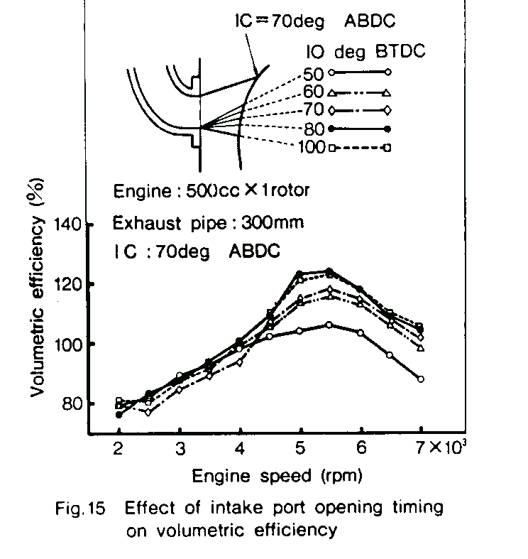
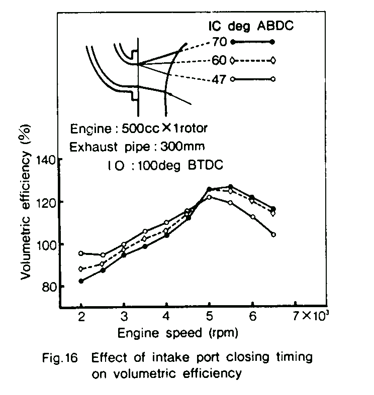
I don't really think two degrees makes all that much difference John.
Here are some charts from Mazda that supports that contention.

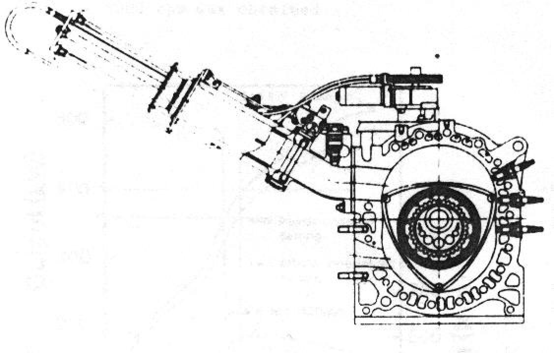
If you want plenty of power scale it from this Leman engine drawing.

Paul Lamar


The AirCraft Rotary Engine NewsLetter.              Powered by Linux.
ACRE NL web site. Copyright 1998-2002 All world wide rights reserved.
http://home.earthlink.net/~rotaryeng/            http://www.linux.org