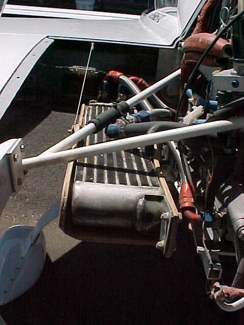
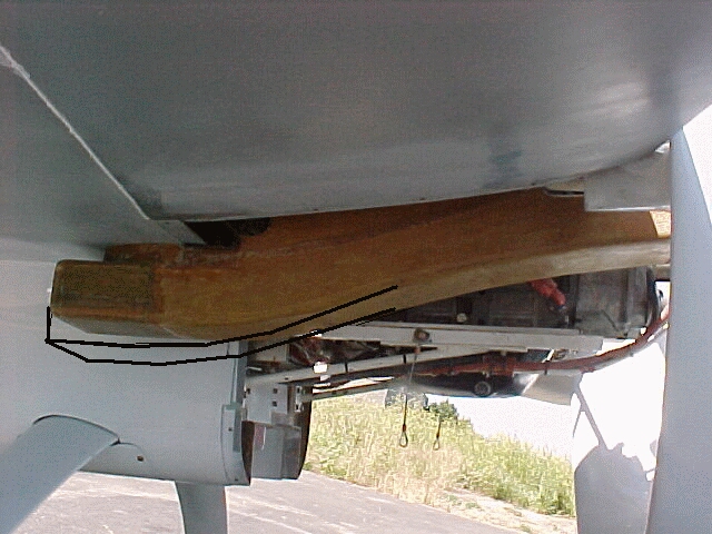
Surprising as it may seem this is what it takes to equalize
the air flow through the core. Not very intuitive at all
is it?

Paul Lamar
Perry Mick wrote:
You have some photos of my oil cooler inlet duct?  That
is the shape I tried to create, feeding the oil cooler in the
looong direction.
I think so. Is this it? I don't know what is going on with your
oil cooler as I have not measured any of the pressures surrounding it.
With that ducted fan in close proximity some strange things
could be happening. You need to instrument that setup with about
a dozen pressure taps. I know you have no room in the cockpit
for a two foot water manometer and you don't want to take the
time to make a solid state data acquisition system so try this.
Use one pressure sensor and plug and unplug it one tap at a time.
You may not have room for velocity rakes so just use porous
foam pressure taps. I suspect the problems are on the outlet
side. Now that I think about it I am almost certain that is where
the problem lies. Since that oil cooler is so close to the
top wing skin the back side is being restricted and the pressure
is transferring to the front side and then to the duct opening.
Consequently the duct is not working at all.

Think about some sort of cowl flap for the oil cooler on the
top of the wing skin. Since that oil cooler is so close to
the top wing skin a small version of Mike Hirshfeld's venetian
blind cowl flaps might do wonders. I would almost bet this would
work without your  measuring any of the pressures.
I'll do a 3D of what I am talking about.

Got any pictures of the latest outlet from the oil cooler?

Paul Lamar
Actually I was just thinking of buying a couple of those
solid-state pressure sensors from Digikey.  In addition
to cooling pressure measurements, they could help me
figure out what is going on in my fan/duct.

No pictures of the latest but here are some marked up
photos.

The first shows how I enlarged the inlet, from a 5" wide
by 2.5 inch high opening to about 5" wide by 4.5" high.

In the second photo, that big opening in the left side is
now closed off in a trailing edge.  I gained 100 RPM by
doing that, less fan interference with the cowl.  Then
in the top cowl above the oil cooler I put about ten slots
1/4" by 5".  The third photo shows the oil cooler as it
looks with the top cowl off.

Those slots apparently weren't enough exit area, so I
had to remove that upper center cowl piece shown in the
second photo, to make a big hole at the back of the cowl
again.

Next I want to make a round hole at the cowl near the
fan hub, that is shown in the second photo drawn in.
I am going flying in the morning and taking pressure
measurements with an airspeed indicator before I change
anything, so I have before and after data.

--
Perry Mick
Duckt N7XR
http://www.ductedfan.com
The AirCraft Rotary Engine NewsLetter.              Powered by Linux.
ACRE NL web site. Copyright 1998-2002 All world wide rights reserved.
http://home.earthlink.net/~rotaryeng/            http://www.linux.org