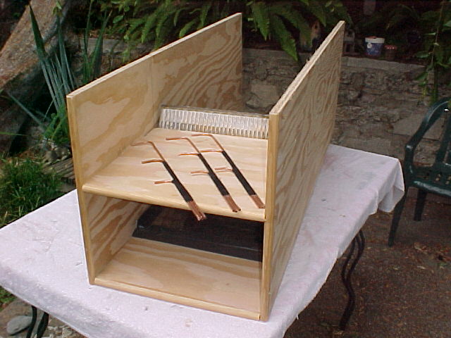
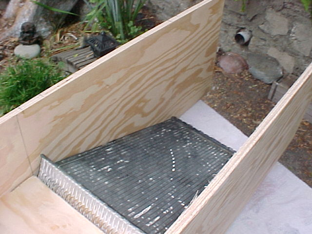
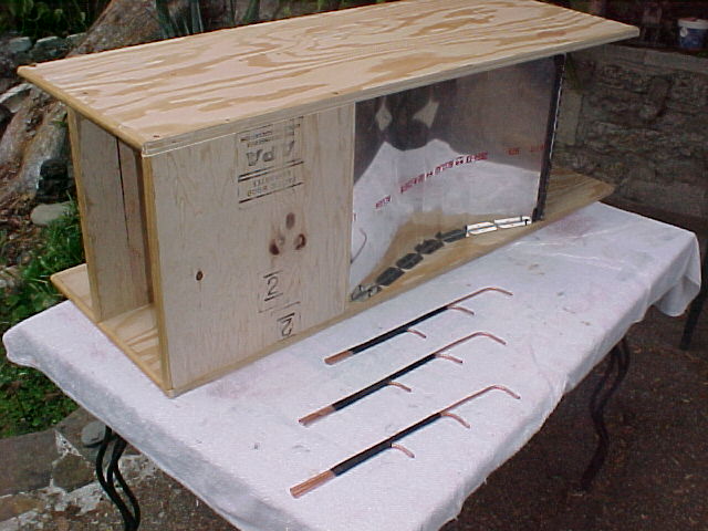
This is made from two pieces of 3/4 ply 18" by 48".
Width is the same as the test rad. In this case
15.5 inches.

The following things can be easily changed:

1: The angle of the rad.

2: The area of the opening by raising and lowering the floor panel.

3: The length of the straight section of duct.
Currently 14 inches. Same as the Ross and Tracy PSRU's.

4: The height of the exit chamber or wall distance back
of the rad. Not yet installed.

5: A cowl flap and its opening angle.

6: The shape of the sheet metal K&M curve causing a difference
in air flow distribution through the rad.

Shown also are the velocity rakes that will be installed behind the
rad. These are made from 3/16 copper tubing from the hardware
store. $12 for 50 feet. Hot glued and taped together for extra
strength. 1/4 inch dia. plastic drip irrigation tubing slips on
this size copper tubing very well.

I will test it first with three sizes of openings and without
the exit chamber and cowl flap.

I used 3/4 half round wood trim to smooth the air going into the duct.
None of this is optimum of course. I just want to get a few
numbers such as rad air flow as a function of input opening area
and effect of back wall distance for future work. It will be installed
on the roof rack of my Dodge Caravan and tested at 80 MPH or so.

Paul Lamar

The AirCraft Rotary Engine NewsLetter.              Powered by Linux.
ACRE NL web site. Copyright 1998-2002 All world wide rights reserved.
http://home.earthlink.net/~rotaryeng/            http://www.linux.org