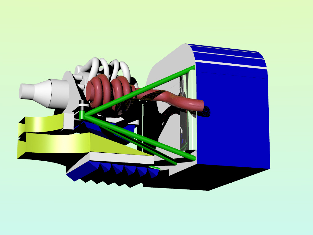
What this K&M graph fig 12-16 is saying is... if you have a wall behind
your
 rad that is less than half the height of the rad away from the
 rad you are paying a severe penalty in cooling flow.
 In other words a 20 inch high rad must be ten inches in front
 of the firewall. Here is a picture of the rad installation
 in the Power Sport RV6. Draw your own conclusions.
 Are you listening Keith and Ray?
Paul,
Interesting curves -- I received the electronic file of chapter 12 today, and
it is interesting reading.

With your rad under the engine, with the sloping oil pan only a few (3?)
inches away from the back of the radiator, won't that cause a flow
maldistribution also?

Bill Schertz
KIS Cruiser #4045
I hope you taperd your oil pan. Opps I see you did not. First
is yours. Second is mine.

Not to worry just make your rad a bit wider and move it as low as
you can get it.

Paul Lamar
Not to worry too much Bill. Unlike the test box on the Dodge and
the Power Sport mount on the firewall the air out of the back
side of the Kis rad can go around the sides of the pan. It is not
as restrcted as it would be in an enclosed duct.

Paul Lamar
Bill, here is something that might work even better. Same size rad.
16 by 22 by 2.5. The inlet scoop area is 15 by 5.

Rotate it 90 degrees in the vertical axis and put the inlet duct
on top. Use venetian blind cowl flaps on the bottom.
When the flaps are open the back of the rad then becomes totally
unobstructed. When closed of course you get external diffusion
ahead of the scoop and the consequent streamlining.

The inlet duct length gives room for a K&M style curve.
A incidental advantage is it shields the rad from the exhaust heat
radiation automatically. Should fit in the stock cowl.
Although the bottom of the airplane is generally higher pressure
the pressure is always lower behind a cowl flaps.

Paul Lamar

The AirCraft Rotary Engine NewsLetter.              Powered by Linux.
ACRE NL web site. Copyright 1998-2002 All world wide rights reserved.
http://home.earthlink.net/~rotaryeng/            http://www.linux.org