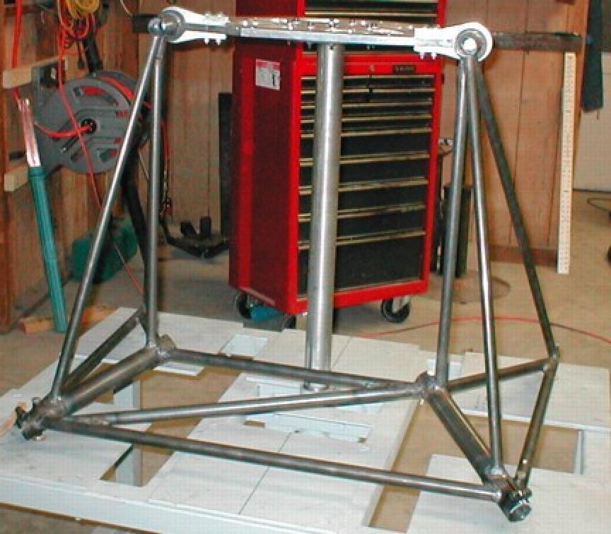
Paul!!....."Very impressive clever trick" ;)

The thing to keep in mind is that the loading
(Stress)
doubles on the remaining diagonal tube, both in
tension
and compression and should be sized accordingly.

                                            Butch
Good point.
Unfortunately I don't know what the lateral load is
sorry to say :-)
The British think it is zero. They never braced their
Merlin mounts laterally while the Americans added
a bit of lateral stiffness to the P51 motor mount.
Even Cessna relies on the bending stiffness of the
tubes
to provide laterally location.
If you kick the rudder you get a bit of yaw
acceleration on
the engine mass.


Paul Lamar
*********************************************************
I would guess that a 45deg banking turn while in a 45deg
dive should be a good start, or 6 Gs on a 45deg vector
angle at the diagonal tube.......Whichever is greater :)

                                        Butch
You mean a side slip? If it is just a 45 degree banking turn
only the wings are going to support 6G's near perpendicular to their
surface. And maybe they too will break off :-) That would be a pure download
on the mount.  In any kind of spin there is a centrifugal load
on the engine tending to keep it straight ahead and the mount
loaded in pure tension.

Now if you lost your vertical tail and the airplane suddenly
rotated side ways then you would see a momentary high side load on
the mount due to a sudden great increase in fuselage
drag and it would probably break off sideways.

A similar but more severe scenario happens in an aircraft with even higher
G's when the horizontal tail breaks off. The airplane pitches down
90 degrees and the wings break off downwards. Typical
in flight break up mode.

I could be missing something but I don't see it Butch.

Lest someone think I am arguing  against lateral location nothing
could be further from the truth. I am with my fellow  Americans on this.
All my mounts will take at least 3 G's lateral.

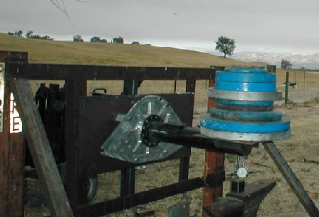
If anyone is in doubt about the strength of one of these
mounts I have had a drawing of a static test on the web site
for the past four years showing the motor mount and fuselage
used as a lever to lift the 1800 pound end of a car.

So far I have heard from no one that has taken this particular
challenge so please... by all means static test your motor mount
any way you see fit.

Much to Jerry Hey's credit he static tested the motor plate
to 600 foot pounds and it passed with flying colors.
Twice the load it would see using a wood prop at a 60 degree
per second pitch rate.

Jerry, can we use your Tailwind fuselage laid over 90 degrees
to test the lateral strength of  that Tailwind motor mount
you just completed? We can use most of the same weights you
used to test the motor plate but placed on the tail for more
leverage. I'll fly up and help.

Paul Lamar

The AirCraft Rotary Engine NewsLetter.              Powered by Linux.
ACRE NL web site. Copyright 1998-2002 All world wide rights reserved.
http://home.earthlink.net/~rotaryeng/            http://www.linux.org