Tom Kendall wrote:

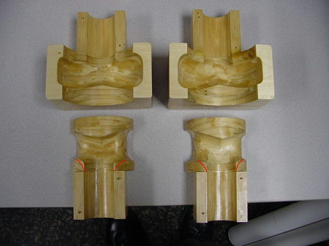
Here's some photos of the completed pattern for the 20B intake
manifold.

Some details:

The boxy looking items are core boxes that are used to make
the sand
cores. I've split them open along their parting lines and
laid them
out so you can clearly see how the 6 ports (2 per rotor)
will each be
supplied by a single, oversized runner.

The parts that are painted black on the main pattern
represent where
the cores will be and will
*not* exist on the finished piece.  However, you can think
of the three big black cylinders as
being the runners.  That is where they will stub in.

I've located some aluminum brazing rod that will make it
very easy to
connect assembled weld bends (or pre-bent pipe) into sockets bored
into the manifold casting.  This will eliminate the risk of
ruining a
casting and/or runner due to the differences in thickness, while
keeping the advantages of a good tight metal-metal joint (I
just don't
trust Devcon or similar for my pressurized air/fuel mixture!).

Note that the runners will be routed over the centerlines of each
rotor housing, and that all bolt heads will be readily accessible
without any tricks.  Also, by keeping all faces, machining,
and boring
operations to easy right angles, the boring and drilling
can be done
on a home drill press! All I need the machine shop to do
is clean up
the mounting face.

So... what shall I do with this gang?  I'll probably get
one cast now
and try it out (Barney's?). After that, anybody else interested?

Tom Kendall
If it is possible to remove some material it might flow better with a
bigger radius on that inside curve as I have drawn on that attached JPG.
Also could we cut one in two and have one for a 13B and one for a 6.5B?
We would have to weld on an extension to replace the missing flange
edge.

Chuck Dunlap
The AirCraft Rotary Engine NewsLetter.              Powered by Linux.
ACRE NL web site. Copyright 1998-2002 All world wide rights reserved.
http://home.earthlink.net/~rotaryeng/            http://www.linux.org