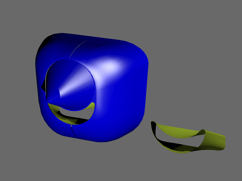
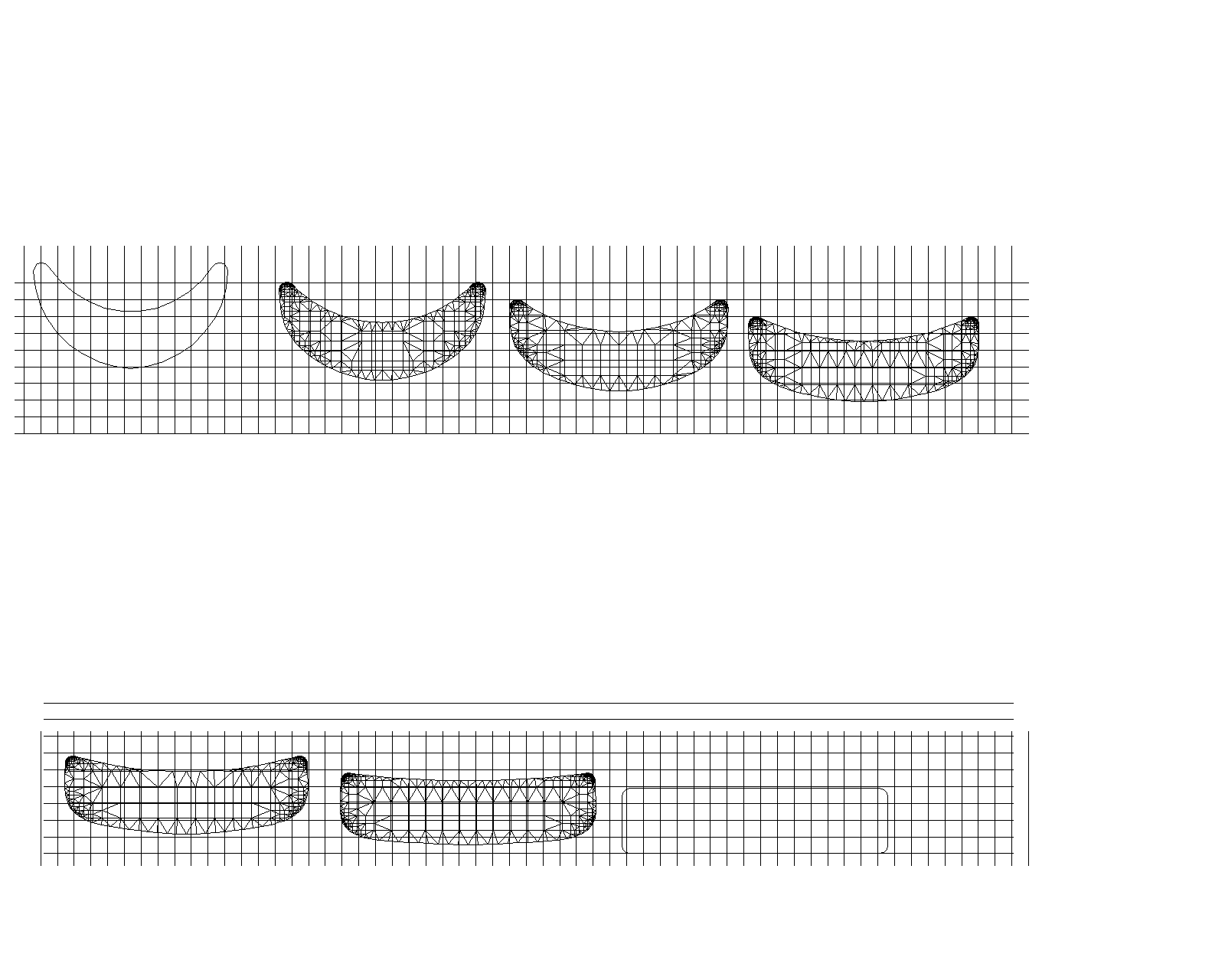
We have to deal with this sooner or later so here is one
way of doing it. These are section drawings two inches
apart. The lowest horizontal line is the base line.
The grid is a one inch grid so you can scale from that.

Back in the old days we had a big plotter and I could plot
these full size as paper patterns. These are small enough you could
take them to Kinkos and enlarge them until they were full size.


Once you scale these from the grid you could cut them out as paper
patterns and glue them to plywood. Tack on wooden  or phony wood
(plastic molding) fairing strips and cover with truck tire inner tube
rubber or sheet rubber stapled on. Use that as a male mold and
make a top and bottom out of fiberglass.

These sections are off set horizontally
because Jerry hey offset mounted his rad. The job of this
duct is not to diffuse the air (raise the pressure) but merely
to conduct it from the front of the cowl to the open end of
the wedge shaped diffuser located on the top of the radiator. As
such the area along the duct should be near constant.

Cowls can be made the same way more or less but female molds
should be made.

BTW in case you were wondering the rest of a tail wind cowl
not shown here can be made with simple curved flat sheets.

This is the first of many such possible ducts if one wants to
optimise one's cooling system.

I am wide open to other suggestions for making 3D ducts
and cowls. Lets hear some other ideas.

BTW does anybody know the number for white is in ACADR12.

Paul Lamar

The AirCraft Rotary Engine NewsLetter.  Powered by Linux.
ACRE NL web site. http://home.earthlink.net/~rotaryeng/
Copyright 1998-2002 All world wide rights reserved.