One of my favorite old books is called "Your Wings" by
A. Jordanoff... Funk & Wagnalls... 1936.

It is a wonderful well written combination of illustrations,
math and simple physics.

*********************************************************************
THE PROPELLER

   The forward speed of the plane is possible because of the pull (thrust) of
the propeller. It is this thrust that overcomes the drag (air resistance), the latter always acting
in the direction opposite to the path of flight. The propeller consists of two or three blades,
according to the particular purpose it is to serve.

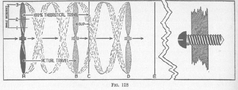
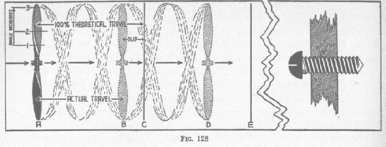
The cross-section of each blade is identically the same as the cross-section of the wing of a plane;
therefore it represents an airfoil to which a rotary motion is imparted by the motor. The blades are
set at an angle formed between the
blades and an imaginary surface to which the motor's shaft is perpendicular.
This angle is greatest close to the hub of the propeller and gradually decreases
toward the tips (Fig. 128). The angle at section 1 is greater than the one at
section 2. The angle at section 2 is greater than the angle at section 3.

 While the propeller is being turned by the engine, it bites into the air and
acts in the same manner as any screw driven into solid material. At each revolution of the propeller
its inclined blades strike the air, producing lift, which in this case we call thrust, and resulting
in forward motion to a definite distance determined by the angle of the blades and the diameter of
the propeller.

If the propeller were turning in solid material, as is the case with a screw in
wood, it could act without slipping, and so the distance traveled in one revolution would be equal
to the theoretical travel of the propeller. Inasmuch as the propeller is turning in the air,
however, there is a certain amount of slip; therefore its actual travel distance falls short of its
theoretical travel distance.

In the illustration (Fig. 128) the propeller at point A in one revolution should reach point C if
there were no slip; but as the slip cannot be eliminated, the
actual travel of the propeller will be from point A to point B. In two revolutions the propeller
will travel the distance A-D. The slip in question is a theoretical slip, that is, one which occurs
when the propeller is working at its best when the blades are striking the air at such a small angle
that a maximum
thrust is obtained with a minimum drag (in this case called torque). The
smaller the theoretical slip, the more efficient the propeller is. In actual practise, while the
plane is in flight, the amount of slip in many instances is dependent upon your ability to visualize
what may cause a great amount of slip, and when and why. As you will see later, when the plane is
pulled to climb at an
angle beyond its ability, considerable slip will occur, with corresponding waste
of power and undesirable reduction of the plane's forward speed.


 To understand the working of the propeller, which is a very interesting subject in itself, I will
ask you to try to stretch your imagination and visualize
everything mentally.

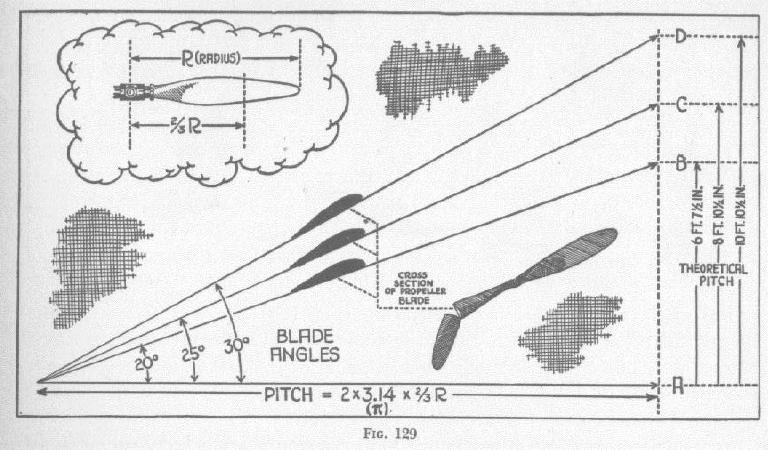
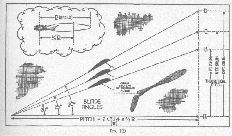
The theoretical distance a propeller travels in one revolution is the theoretical pitch. In the
adjoining illustration (Fig. 129), you will notice that the
theoretical pitch varies with the blade angles as well as the diameter, as stated
before. A ten-foot propeller with blades set at an angle of twenty degrees will
travel forward in one revolution about six feet seven and a half inches, and so
on with distances A-B, A-C, and A-D, respectively.

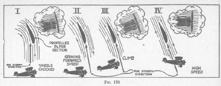
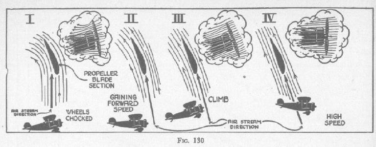
 FIG. 130. In this illustration the plane in position I is blocked, and let us as
sume that the motor is wide open. The propeller draws a mass of air to which
it imparts a certain backward speed. As soon as the air particles pass the propeller blades they
have the tendency to follow a path such as shown in the
illustration. While the plane is stationary its revolving propeller meets the
air at the greatest angle of attack, which is far beyond the most efficient angle.

As the plane gains speed over the ground prior to the take-off (II) and as the
blades gradually bite into the air, the backward motion of the air decreases
and the angle at which the propeller strikes the air decreases. During the climb
(III) the forward speed of the plane is still greater than the speed prior to the
take-off (II) . Therefore the propeller blades meet the air at a smaller angle of
attack, and if the plane is then placed in a position for high speed, the angle at which the blades
strike the air becomes a minimum or closer to the most efficient angle of the propeller, and the air
particles pass by the propeller blades in a manner such as shown in position IV. The theory of the
propeller is very involved, but for practical purposes a good mental picture is helpful.

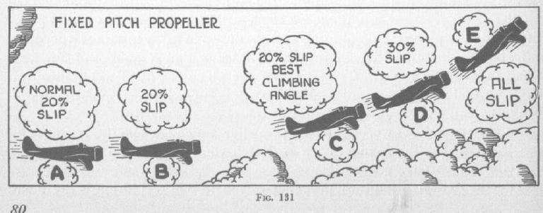
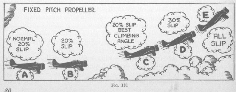
FIG. 131. The FIXED-PITCH PROPELLER is the kind whose blades remain with
a permanent angle the type of propeller we are using on the plane during the
present stage of your training. The work the propeller performs is measured by
multiplying its thrust by the number of feet the plane has traveled per second.
Thus, if a plane is traveling two hundred feet per second (about one hundred
thirty six miles per hour), and the propeller thrust at that speed equals a drag
of nine hundred pounds, the foot-pound work of the propeller will be one
hundred and eighty thousand pounds. If we divide one hundred and eighty
thousand by five hundred and fifty, we obtain the propeller-thrust horse-power. In the case of the
above example, this power will be about three hundred and thirty-three horsepower. As the normal
propeller efficiency is about
80 per cent, the motor should deliver to the propeller about four hundred and
nineteen horsepower.


   The normal propeller slip, which we have arbitrarily accepted as 20 per
cent, will remain the same if the plane is flown in such a manner as to maintain this figure. In the
illustration, plane position A at cruising speed has a
normal propeller slip. In a slight climbing position, as in B, the slip will remain normal if we
slightly increase the motor output. The C position will further maintain the normal propeller slip
if we increase the motor-power output. On the other hand, if by this time the engine throttle is
wide open which means
that we cannot obtain any more power and the plane is forced to climb at a
steep angle, as in position D, the rate of climb will be smaller than when the
plane was at position C, because the slip of the propeller in position D has
been increased to 30 per cent. The power of the motor, nevertheless, is
absorbed by the propeller but not converted into climb or forward speed. Position
E shows the plane at an extremely large angle, not of climb but relative to the
ground, as the plane in this position has ceased to climb and for an instant will
lose all its forward speed and be in a stall.


The AirCraft Rotary Engine NewsLetter.  Powered by Linux.
ACRE NL web site. http://home.earthlink.net/~rotaryeng/
Copyright 1998-2002 All world wide rights reserved.