Aden wrote:

Greetings Paul
I have been reading the questions and comments regarding CDI power requirements.
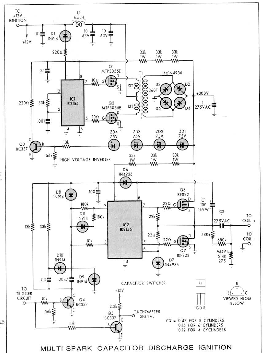
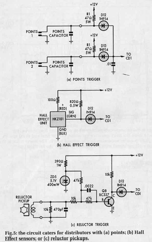
Attached are higher resolution .JPGs of the circuits which should be easier to read and/or post.
As you may recall, one of these units was built in a modified form for ionising gasses, and power
consumption data was taken at that time. This application required an adjustable Extra High
Tension (EHT) voltage, and a variable spark rate, and so the measured data includes a range of
output powers.. The results do not support the linear power consumption with RPM shown in your
graphs, but this is because of the multiple spark nature of the circuit - otherwise I agree with
you and the graph - lower power input than a Kettering system and a linear increase in input
current with RPM. This must be so due to shorter spark duration and reasonable (low) invertor
losses. (area under the curve of voltage with respect to time being proportional to power). More
about that later. First a word about the data taken at the time.
The tests required replacement of the trigger circuits with a trigger generator to allow
adjustable spark rates between 10Hz and 1kHz., whilst supply current measurements made at each of
these frequencies.  Additionally, the EHT voltage was adjusted by modifying the feedback network
(by shorting out one or more of the 75V zener diodes), and measurements were taken at reduced
spark energies.  In each test, a standard Bosch coil and spark plug was used to produce
multiple1/4-1/2" long sparks, at atmospheric pressure, and did so at substantially reduced EHT
voltage and coil energy. With all 4 zener diodes in circuit, the coil primary voltage is 4 x 75V =
300V - the unmodified configuration.
The energy available to the coil primary varies as 1/2 X C X
V X V, so by shorting out one of the zener diodes, the primary voltage reduced from 300V to 225V
i.e.: 75%. Thus the coil energy reduced to 0.75 squared=56% - about half. Note that at
such reduced voltage, huge sparks were still obtained, ~ 0.5" long, without misfire, under STP
conditions.  I read and note that high pressures (i.e.:compression pressures) require  higher
voltages to ionise gasses. Finally the data, multiple spark mode  :)

#Shorted       Max rate      Min rate      Power
0                    6.6A            1.2A          83/15
1                    5.6A           0.9A          70/11
2                    3.6A           0.6A           45/7
# shorted refers to the number of zener diodes shorted, where 0 shorted means full power. The
power figures correspond to supply power at max. rate (eg.83W) and min. rates (15W) respectively.
Min rate was 10Hz, max rate was 1kHz.You say (in a prior post) that the rotor fires once per
output shaft revolution, thus 10 Hz = 600RPM, 1kHz=60,000 rpm!
I note that the input power does not follow the expected inverse square law mentioned above, but
rather in a  discontinuous non- linear way due to the multiple spark feature of the circuit.
Consideration of the number of sparks produced when frequency is raised from 10Hz to 100Hz (6000
rpm)gives an expected calculated supply current of about 1.8A per plug;  multiple
spark, unmodified.
The point of me mentioning the reduced EHT voltage is that I read somewhere that the plug gap for
the rotary engine is small (0.016"?). This seems small in contrast to my passenger car (Chev. 6
cyl) which uses EFI and a plug gap of 0.037". Given the capability of this unit to produce very
long sparks, then if a small plug gap is used, then the voltage required to fire it will be less
than that required for the larger plug gaps, and accordingly, the EHT voltage can be reduced with
consequent savings in input power. Also, given two plugs per rotor, multiple sparks would seem to
me to not offer any major advantage and single spark operation would reduce input power
dramatically.
Finally, a word regarding  Tracey's reservations about  the benefits of CDI. Experience is worth
more than many words. I believe his position is that:-
1.  No advantage is gained by leaning further than the existing Mazda ignition is capable of
firing. This was determined by testing.
2. No significant increase in power is obtained by using CDI over the Mazda system.
3. He has reservations about the reliability of relatively complex high power electronics in an
arduous environment.
Point one; considering Tracey's accomplishments and experience, I take this as a given.
I can confirm point 2 in passenger cars.
Point 3 is my experience also, having made and used 3 different CDIs in passenger cars. The unit
that I constructed from the circuit attached failed and destroyed one of the output transistors
when trying to draw long sparks (over half an inch long) whilst using a coil without an internal
spark gap. This failure mode requires such a coil, and could then occur if a plug lead failed or
became disconnected. Most coils have internal spark gaps. The use of a VDR for protection in the
circuit is not the most suitable application for VDRs. This reliability view  though, (I think
Tracey would agree), can be overcome with testing and redundancy.
As I see it, the perceived advantages of CDI are:-
1. Consistent  spark energy  at very high RPM relative to street cars. You (Paul) and other
racer's use support this view. What RPM is relevant here? Above 5000, 6000,7000..... RPM?
Certainly, spark energy is consistent. Certainly, Kettering ignition did not work for me at
5000RPM on a V8.But how relevant is this given multiple units each firing one plug at say 7000RPM
(=7000 sparks/min) versus 8 plugs at 5000RPM (=20,000 sparks/min)?
2. Easier starting at low supply voltages as would be expected when cranking. Easier starting than
the Mazda ignition.  I don't know. Is this a problem?
3. Ability to fire fouled plugs. A very real advantage in view of the fact of reported problems
with 100LL, and supported by published data and by many opinions. If you see this unit working on
the bench, the huge, mean sparks would lead you to believe that this unit would fire any fouled
plug! Reducing the EHT voltage however would reduce this capability.
4. Lower power input. Yes particularly under failed alternator conditions. More so if redundant
ignition systems may be turned off. Given a 40 A-H battery at the 20 hour discharge rate = 2A for
20 hours  means 20 hours of operation per multiple spark system per plug. Thus around 5 hours for
4 units assuming a fully charged full capacity battery.  Perhaps twice this for single spark
units.
Paul, I will be retrieving the prototype unit in the next few days. Are you (or anyone else)
interested in single spark power consumption measurements.  I can do this.  Would shipping a
working unit to you to evaluate (on the dyno) be of interest?

Thanks for the newsletter.
Regards to Robin.
Aden
021020
Yes I would love to have it and I can reimburse you for any
cost. We could also test a Paul Lipps type fast MSD system.

Paul Lamar

The AirCraft Rotary Engine NewsLetter.  Powered by Linux.
ACRE NL web site. http://home.earthlink.net/~rotaryeng/
Copyright 1998-2002 All world wide rights reserved.