Paul,
Enclosed are some pictures of my water pump mods and use of 1-3/8 tubing in
combination with Wiggins for the plumbing.

021_18a is the modified water pump before welding.
022_19a are the tubing sections to fit between the radiators and the pump

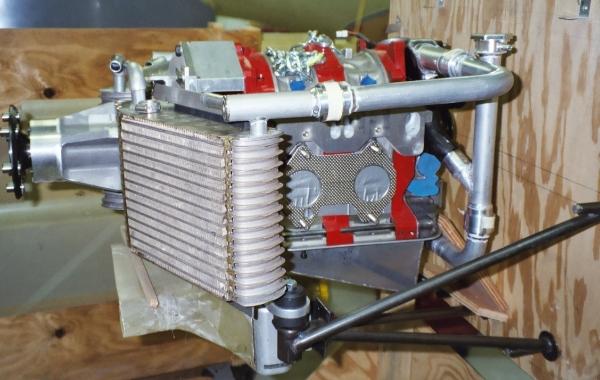
023_20a2 shows the piping in place from the manifold side.  The output of the
water pump is sent to the left radiator, and splits into two streams, one
going into the left rad, and the balance going into the right rad (parallel
flow).

024_21a is a frontal view, with the hose interconnect barbs visible.  Water
exiting the first radiator flows through a 3/4" hose to join the water coming
out of the second radiator. If I make the hoses equal length, the flow should
be balanced between the two rads.

025_22a is closeup of the fitting that splits the flow. It is not welded into
place yet. The small hole in the end of the fitting is tapped for a pressure
probe.  I will be able to measure differential pressure across the radiators,
and therefore the flow rate.

026_23a shows the plug side piping.  An extra Wiggins fitting (total of 5) is
used to allow the tubing to be installed easily.  Tubing is held in place by
clamp to the oil pan bolts.

In this scheme,
a. All rads and tubing float with the engine,
b. Flow is in parallel,
c. I am relying on the Wiggins to handle small changes in positions, etc.
d. A stress relief bracket will be installed to remove any cantelever load
from the fitting welded into the top of the Radiator.
e. pressure and temperature across the radiators can be measured when I ever
get the engine running.  Still a long way to go.

Bill Schertz
KIS Cruiser #4045
Very nice work Bill. Looks bullet proof. When you get this thing
flying you are up for best rotary engine installation award hands down.

Paul Lamar

The AirCraft Rotary Engine NewsLetter.  Powered by Linux.
ACRE NL web site. http://home.earthlink.net/~rotaryeng/
Copyright 1998-2002 All world wide rights reserved.