Dean Head wrote:
Paul,
Has there been any published calcs on the inlet area of a P-51 belly
mounted
for long ez/Cozy family?
Thanks
Dean
The original scoop on the Long EZ was the P51 type. The dimensions
should be on the Long EZ drawing. Does anybody have a copy lying
around?
Paul Lamar
Paul,
Are there any guides for calculating inlet area to get enough air flow and
sufficient differential pressure to cool the 13b. I realize this is
probably(surely) directly proportional the area and pressure drop across
the
rad and oil coolers. Also, I assume I would use climb out as the entering
velocity of the air. Not sure what to use for the cowl exit pressure to
determine the DP. Atmospheric should be a conservative starting point.
Maybe
if this data is not in one place I could gather it together into a
spreadsheet for others to use.
Thanks
Dean
We have been working on this for four years Dean :-)
All of the above is correct. My starting point is 30% of the core area.
I have been working on people to reduces the cowl exit pressure
by using cores mounted adjacent to the skin using louver type flaps.
This is some recent work on the subject which perhaps you missed.
The big problem is getting the data on the efficiency of the rads.
We need some real world measurements of the temp of the air exiting the
rads.
You can use the assumptions and math out of this QB BASIC program.

Paul Lamar
Paul,
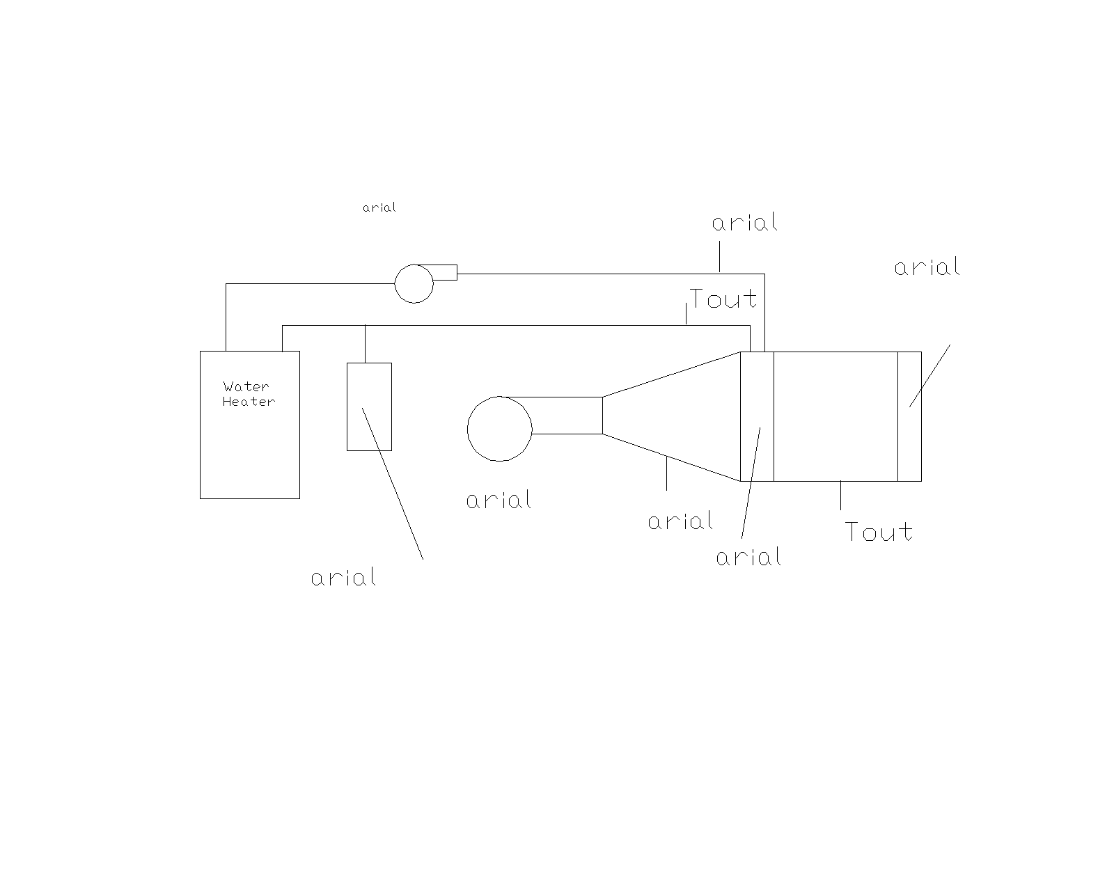
I agree with needing the empirical data. I had thought to assemble a small
water heater closed loop system to test such. Air flow measurement is the
tough one but I have access to a device of sorts. I also thought that this
whole concept could be added to your mobile test rig by plumbing the rad
under test in place of the cars heater core. A couple of t's and ball
valves. One of the guys on C-A has a Leze scoop, I might buy it off him and
rig it into a mobile evaluation setup. As for a good guess on what size rad
to start with I think I'll just pick one that looks like it will fit back up
under the engine inside the stock cowl. There are just so many
possibilities. Obviously we know Tracy's evaps work. That could be a
starting point. Not to mention all the possibilities with custom designs.
Thoughts?
I attached a block diagram of test set up thoughts. Closed loop water
eliminates some of the earlier discussed issues.
Dean
"plumbing the rad  under test in place of the cars heater core"
Yes we thought of that quite some time ago but we would have to tow a
large trailer to get enough heat out of the engine. At 85 MPH my Van
is getting about 18 MPG so that is 4.7 gallons an hour. 85/18. At
a BSFC of 0.4 (really giving it the benefit of all possible doubts) that
works out to about 70 HP max. Not really in the ball park for an aircraft.
Also a bit too much trouble. The Dodge Caravan will over heat if you
run it up a steep hill at high altitude. The cooling system is just
not up to it. Never the less I will get some remote temp sensors and
mount them behind the rad on the Dodge and see what we get.

Tracy's evap cores do not work all that well. He hates to admit it.

His friend Bernie Kerr flies along side in his Lyc RV4 and Tracy has
problems keeping up in certain circumstance due to overheating.
I have flown with him and he backs off in climb when it starts to
overheat. Also a top speed run gives him trouble and I think that is
why he is reluctant to enter the Sun 100 race despite the fact there
is $250 in it if he can average over 200 MPH for twenty minutes.
I have seen him average over 200 for a few minutes.

IMHO not all of Tracy's problems have to do with the evap core per se.
The left evap core is inches from the red hot exhaust so it is
absorbing radiant heat. We have mentioned this many times on
here but Tracy apparently has decided to ignore it.

The evap cores themselves are placed too close to other obstructions
under the cowl such as the gear box and engine. This tends to
cut the flow as impact pressure builds up on the obstructions
and reflects back through the cores. It is absolutely essential that
the back side of the cores be totally unobstructed.

Tracy tells me he is trying to build a subsonic ram jet by heating
the air and squirting it out the back. This of course is doomed to
failure because the back pressure on the rad reduces the subsonic
air flow through the rad limiting the amount of heat that can be
transferred to the air. He is attempting to counteract this by
making the rad air intake holes larger and larger. Face it Tracy! LOL
It is not going to work!  No hot air.... no ram jet!

He refuses to put a cowl flap on it as he claims he is perfectly
satisfied with the way it works now. IMHO he is in denial.

It will be interesting to see what he winds up with on his 20B
powered RV8.

BTW I had to load that dwg file into Rhino and then export it
as a ACAD R12 file so I could load it into ACAD R12 and plot
it as a gif. You would think that silly ACAD could export ACAD R12
files directly.

Paul Lamar

The AirCraft Rotary Engine NewsLetter.  Powered by Linux.
ACRE NL web site. http://home.earthlink.net/~rotaryeng/
Copyright 1998-2002 All world wide rights reserved.