Paul,
Here are the photos I'd promised.
01 the modified evaporator cores. Left- mitsubishi core
Middle- Harrison. Right side- From a late 80's astro van.

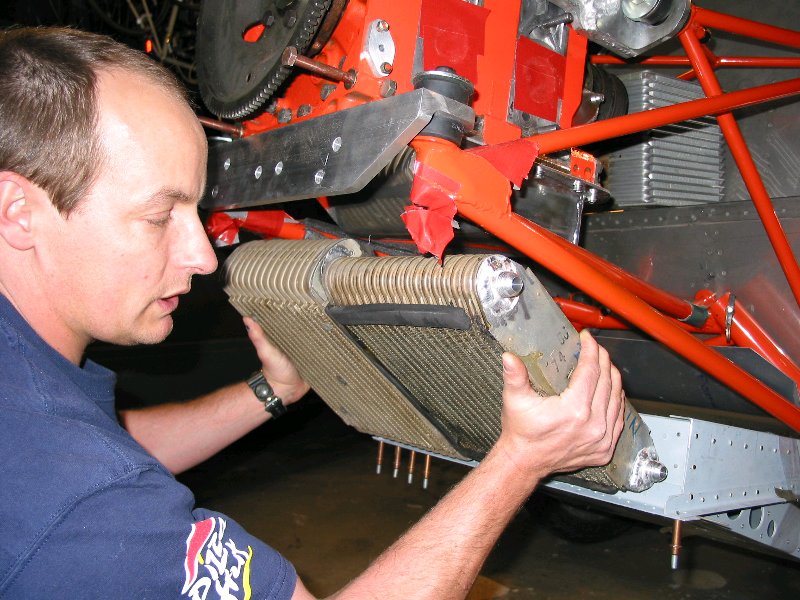
Left side view of engine. Cowl flap structure will be braced to firewall. Note the placement of the oil cooler against the engine. I'm thinking that a scoop on one side of the cowl providing air and one on the other side exhausting air from the oil cooler should do the trick. Of course, there will be a well sealed duct feeding and exhausting the oil cooling air. I could use this exchanger to provide cabin heat and defrost air.
Hair club for men candidate holding the engine coolant heat exchangers in the proposed position.
Cowl flap. This will be in flight adjustable with a linear actuator from Mcmaster-Carr.
I know that these photos raise as many questions as they answer. I'll try to anticipate a few and answer a few ahead of time

- The intake manifold is not in it's final form. I'm working on lowering it. Still a work in progress.

- Coolant to the heat exchangers will be fed by an an 16 line that splits into two AN 10 fittings, and back to the engine by two AN 10s into one AN 16.

Exhaust headers will run out through the cowl flap, it'll be tight, but with a lot of work fitting and sheilding, I believe it is safely do-able.

The cowl will be similar in appearance to Mike Will's cowl.

Feel free to pick this apart, I'd rather be picked apart on the ground than picked up in pieces off of it.

Brian Trubee
Brian sent a few more but all of these are too much to publish
all at once. Nice motor mount and Schertz Beam Brian.
I am not so sure about the evap cores :-) Might work.

Paul Lamar

The AirCraft Rotary Engine NewsLetter.  Powered by Linux.
ACRE NL web site. http://home.earthlink.net/~rotaryeng/
Copyright 1998-2002 All world wide rights reserved.