C M Smith wrote:
Paul,
The table looks good. For quick pump work I use one atmosphere as 15
psi and 30 feet of
water; 2 feet per psi. Plenty good enough for small sizes of pump.

The efficiency of the cast impeller in an automotive paddle pump is
abysmal but it is easy
to cast and there is plenty of HP availble.
C M,
Is there something that could be done to improve the design of the
pump
impeller and possibly the housing to significantly improve this
"abysmal"
factory design? We are far less cost driven than the factory is and I
think
many of us would be willing to invest in an improved design that yielded
a
significant increase in flow and cooling potential. Its been pointed out
by
several people here over the years that the stock pump flow appears to
be
marginal and that the cooling situation could be helped by improving the
flow potential of the pump.

  A couple of years ago Jeff Spitzer proposed to do just that and
supposedly  was prototyping and testing an improved design which he was
then going to make available to us. Unfortunately, nothing ever came of
it.
I havent seen anything posted on here by Jeff in years. Is he even still
on
here Paul?

Mike Wills
Most of the cast impellers in the  Mazda pumps look very good
compared to the sheet metal impellers I have seen in other brands.
Here is a picture of one of the worst Mazda ones. The Cosmo is better.
I think one would be lucky to get a single digit improvements
in the efficiency. After all, centrifugal pumps have probably
been around for at least 200 years.

I think the most important thing is matching the radiator resistance
the the characteristics of the water pump. The block does not
seem to be that big of a retarding force.

Paul Lamar
Actually Guys,

I don't see anything abysmal about this design. Since I have designed these
things before I feel I can give an educated opinion on the subject. Housing
is a nice scroll, It has a nice radiused cutoff with enough clearance to
prevent debris from causing a problem as well as preventing turbulence and
cavitation. The blades have radiused leading edges and are curved.
definitely way better than the average sheet metal flat blade version of the
water pump. not quite airfoil blades, but as close as you can get with the
material and process limitations. I would say that the Mazda engineers did
their homework on this one. You might be able to machine a true stainless
steel airfoil impeller, tailored to the aircraft environment and gain a
couple HP. Unless you are willing to build a pump dyno where you can control
head pressure and measure flow, power absorbed etc. I don't thing tinkering
with this pump is a good way to spend your time. Either the designers of
this pump were just being Japanese, or there is some other reason for
needing a pump that is designed this well. I can't see spending the money
without a reason. Perhaps the flow required is higher or the pressure drop
across the block is higher than your average piston engine. That is another
key piece of info you will need to make any meaningful improvements in the
design. If it makes you feel better, you could use a die grinder to take of
the casting flash and smooth out the impeller.
Cavitation is a boiling phenomenon. To understand it you have to understand
how the pump functions. It works by generating a high pressure on one side
and a low pressure on the other side of the pump. I'm going to use the
somewhat incorrect (especially for centrifugal impellers) analogy of the
airplane wing. It has a high pressure on the bottom and a low pressure on
the top. If the working fluid is a liquid, imagine you fly fast enough for
the pressure on the top of the wing to become lower than the boiling point
of the fluid at ambient temperature. The liquid boils. Small bubbles form.
This is not the problem. When the local pressure once again rises above the
boiling point the bubbles implode with great force. So great that they can
tear away chunks of metal and destroy the pump! THIS is a problem. The
situation I am describing actually limits the speed of hydrofoils. They go
fast enough and they have cavitation on the foils. Bummer.
Oh,  by the way Paul there is a LOT of room for improvement in impeller
design. Unlike axial designs which are pretty well described by napkin type
calculations, centrifugal fan/impeller design is still somewhat of a black
art. The killer is the exit angle determination. Mostly trial and error or
empirical data. CFD has made this easier, but there are no charts to look
this up in. Don't believe the equations in the fluids books, they work for
the final exam or a rough guess, but hardware has a way of embarasing the
black board designer types.

Monty
I totally agree! 27% efficiency is poor. However I don't think any
shade tree mechanic is going to stumble on a 10% efficiency gain let alone
an impossible order of magnitude claimed by some of these charlatans
selling miracle electric water pumps. Can we say perpetual motion?

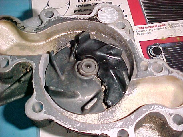
Here is a pic of an injected molded impeller out of a  Mazda V6 piston
engine. Unfortunately as you can see it failed.

Paul Lamar

The AirCraft Rotary Engine NewsLetter.  Powered by Linux.
ACRE NL web site. http://home.earthlink.net/~rotaryeng/
Copyright 1998-2002 All world wide rights reserved.