George Lendich wrote:
Needle bearing can tolerate very high thrust loads but only
at moderate to low RPM's. The big problem is the thrust bearing on
the engine side as it is rotating at 6000 to 7500 RPM  while
the planet carrier is rotating at 2000 to 2600 RPM in the same
direction. A difference of 5000 RPM. Needle bearings don't
like to rotate at those speeds. So you need at least two back
to back on the engine side. Three would be better.
this slows the RPM of each individual needle bearings to
one third of the total.

On the prop side the problem is not so severe as the housing
is stationary of course and the planet carrier and prop shaft
are rotating at a difference of only 2600 RPM. So the stock
needle bearing that came with the Ford planet set is fine.
Do you think a bearing is required between the sun and planetary
housing?
there is sufficient room for a small bearing.
Yes. Absolutely see above.
I haven't figured out how to attach the planetary housing to the prop
shaft
yet -still pondering, any/all advice is welcome.
Well you could use the stock splines or do a trick like Power
Sport does and bolt a flange to the inner end of a thick wall
prop shaft using s slew of small bolts. Then bolt the flange
to the planet carrier with six larger bolts.
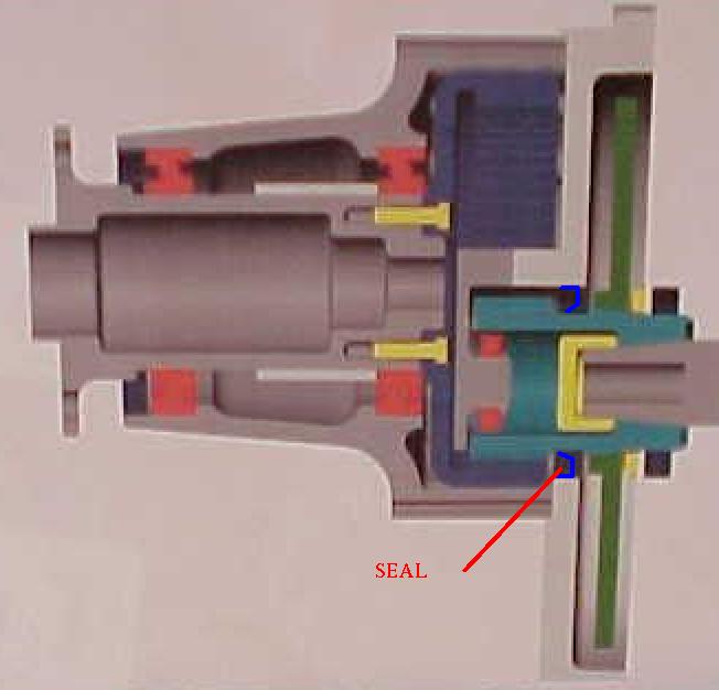
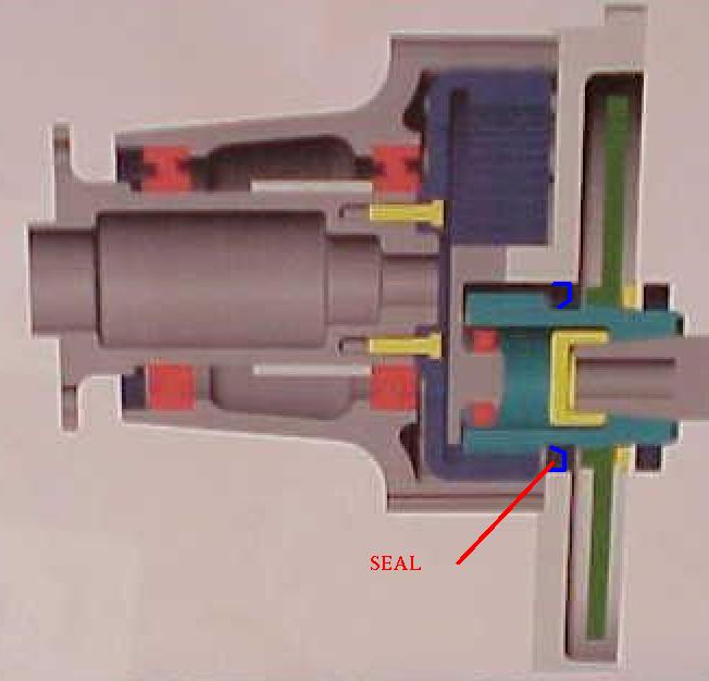
The attached drawing psru5a shows the 2.17:1 configuration where
power is removed from the ring gear. In your case the
ring gear is locked to the housing and power is removed
from the planet carrier.
Also what are the attachment points to the housing ?
I don't follow you here?
George(down under)
George, Please display the drawing on your screen and do the screen
capture trick. Then send us the gif or jpg so we can all read
it. dwg files are not compatible from ACAD version to ACAD version
and it is a lot of work for me to convert them to gifs.
Do I have any volunteers?

Paul Lamar
Paul,
As soon as I figure out how to do that 'screen capture trick' I will send
the drawing again.
Look back about a couple of weeks for the screen capture trick.
If you are using NetScape you can search the old messages. PL
BTW I want to use the splines on the planetary and I was going to use a
steel (thin wall) 3" tube for the prop shaft - as you have previously
suggested. What thickness and material do you consider appropriate for
this!?
If you run the stress numbers you come up with ridiculously thin wall.
Something that would scare  most people. So my guess is you
would feel comfortable with a .20 inch wall or greater.
We are not talking about much weight difference here.
A 3 inch .2 inch thick wall tube six inches long weighs only about
three pounds. PL
So my dilemma is how to affix a male spline of the prop shaft.
Well now that is a problem. If it were me and I had to use the
spline I would find a shop with a really big and powerful lathe
and hog it out of solid billet of 4340.

If it were me I  would not use the spline on the aluminum planet
carrier. It is a source of possible wear and back lash. I would use
the Power Sport bolt trick and a bulkhead bolted to the planet carrier.
I would cut the spline part off the planet carrier.

Perhaps you can talk Power Sport into selling you a prop shaft.
See the rendering below.

(BTW Power Sport, hitting a gear tooth with a steel hammer is not a good
idea. It is a much better idea to hit the gear tooth with a
rubber hammer :-)) A Power Sport prop shaft, one of Tracy's
rubber torque isolators and a Ford planetary would be a marriage
made in heaven :-). PL
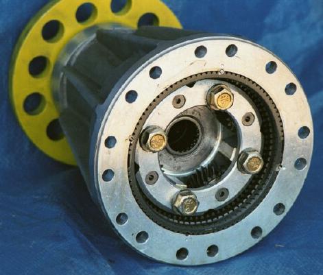
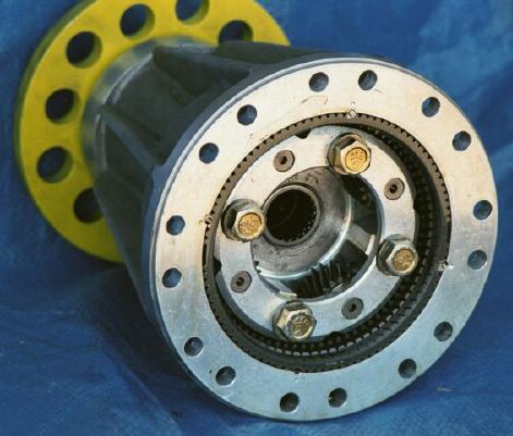
I'm not sure how to hold the ring gear, the outer end surface of the R/Gear
is splined, perhaps this could be utilized ! (see picture) - but this would
require getting a splined female receiver, and I'm considering weight
implications with everything. Perhaps I can have that molded into the
casing - not sure just yet.
The ring gear should be a tight fit in the housing.
Ross just drilled some .25 inch holes around the ring gear and
used pins to lock the housing and ring gear together. See the attached
pic. PL
Didn't Tracy say that the R/G hub is prone to easy breakage (because of the
material)so I don't think I will be drilling holes in that, if this is the
case !!
Well you are not using the stock ring gear bulkhead. That was for the
2.17:1  configuration. I agree with Tracy. The drawing I sent
was obsolete. (I need to fix it.) If I were
making the 2.17:1 configuration with the bolts attaching it to the
prop shaft  I would make a new ring gear bulkhead out of steel.
In your case you are taking power out of the planet carrier and a
simple steel washer like bulkhead bolted both to the shaft
and to the planet carrier would be all that was required.  PL
'What are the attachment points to the housing' i.e. what are the attachment
points on the engine housing that one can attach the PSRU ?
You mean the rear engine end housing that bolts to the transmission
bell housing? PL
Get back to you with drawings as soon  as possible. Thankfully my 15 year
old son is learning CAD at High School, he's way ahead of me in this
AutoCad.
George (down under)
The AirCraft Rotary Engine NewsLetter.  Powered by Linux.
ACRE NL web site. http://home.earthlink.net/~rotaryeng/
Copyright 1998-2002 All world wide rights reserved.