Mark Wrathall wrote:
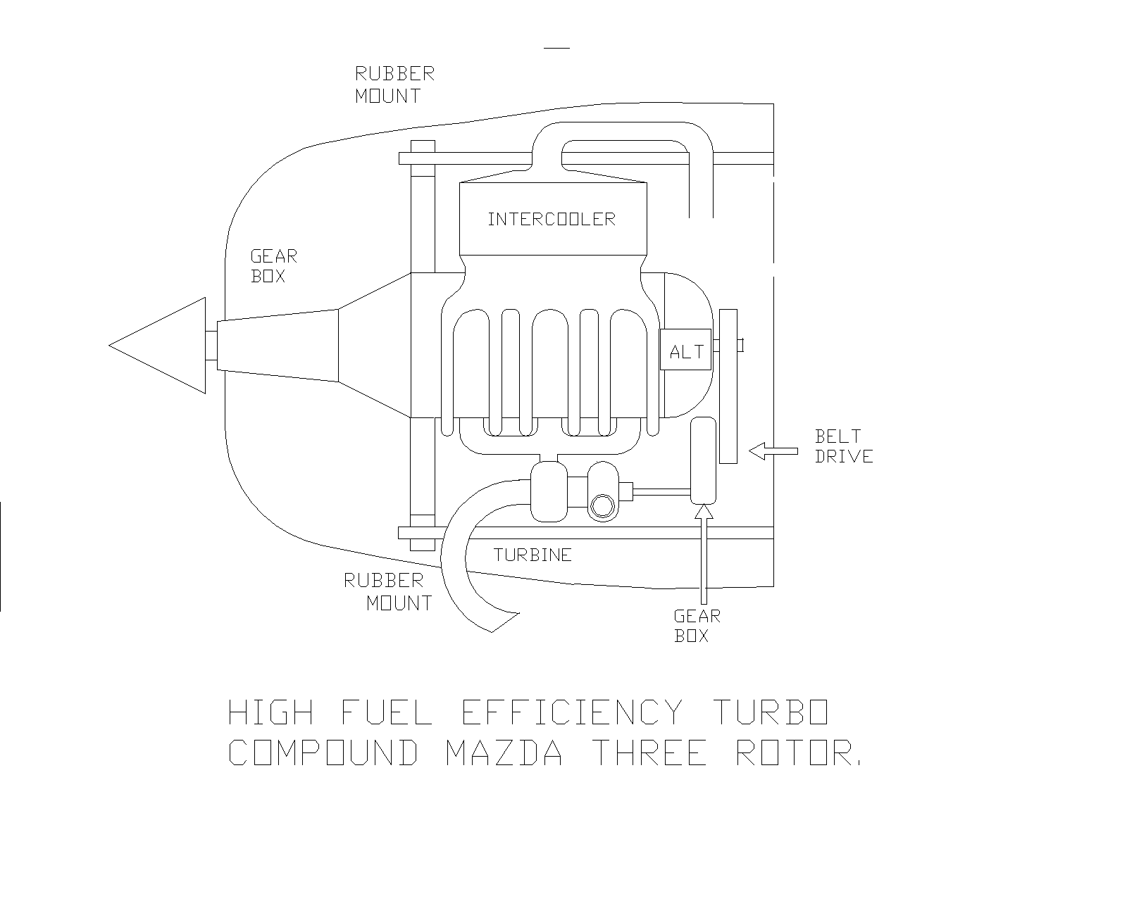
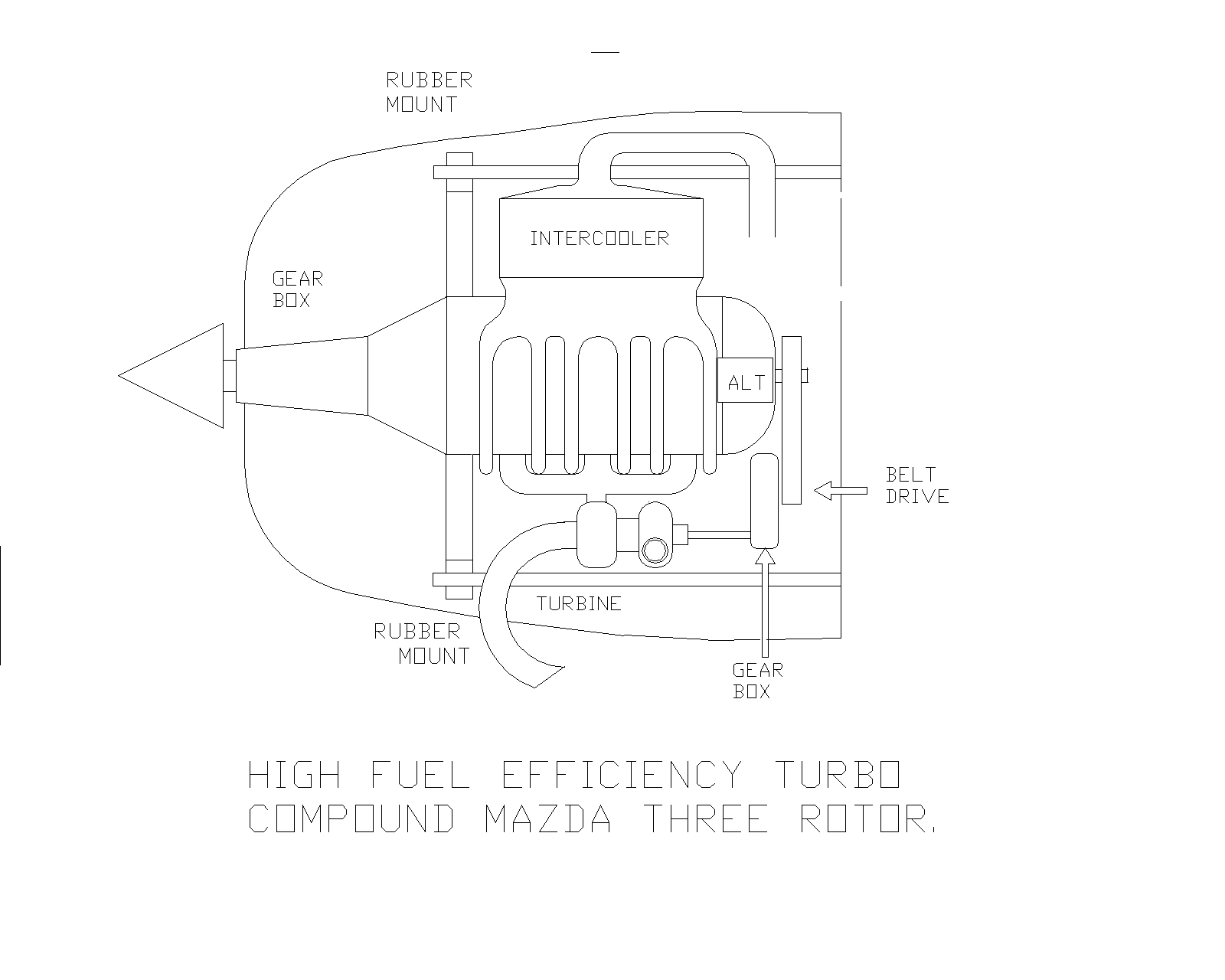
Paul wrote: It is much simpler to do it with a wankel as the engine
is
already
rotating at turbine like speeds so no need for gearing between
engine and turbine, unlike the elaborate gearing that is required
using
a big old low RPM piston engine. Furthermore there are no exhaust
valves to break up and destroy the turbine on the way out.
The Achilles heel of the R-3350 TC.
Paul, I really don't see this working in this form. With the low mass
flow
of an intermittant combustion engine (compared to a gas turbine) you
would
have two choices:

1: porting the exhust on the turbine through a single nozzle covering
a
fraction of the turbines circumference, or
2: feeding the whole circumference via a scroll.

1.With the exhaust ported onto the turbine at one point, you will have
major
durablity issues with the blades due to the 1 per rev thermal shock
coupled
to the one per rev mechanical flexing they will see. If you only drive
the
turbine wheel through a single nozzle covering a small arc, you also
have
aero drag over the rest of the circumference, and large leakage
losses. The
disk will be very heavy.

2. You would really need a scroll (given the diameter, probably
feeding on
rotor in each side of the scroll( to even out the temp and pressure).
For
this the scale here is way off. For the mass flow coming out of a 13B,
your
blades length would be miniscule at that radius. Turbine efficiency
would be
crap. The disk would still be pretty heavy. Will a scroll even work at
that
scale?

What is the mass flow out of a 200hp 13B? What is the diameter of the
flywheel. With that I can do the turbine equations to put some numbers
on
this.
My guess on the mass flow is the weight of air and fuel burned:
10 pounds an hour for fuel and at 12:1 mixture ratio 120 pounds an hour
for air. Does that sound about right. Please run 130 pounds an hour
through your program and see what comes out.
Opps! That should be ten GALLONS an hour. So that is 60 pounds
per hour for fuel and 720 pounds for air for a total of 780
pounds per hour mass airflow. That is more like it.

Paul Lamar
I'll call that 0.1Kg/s.

The example model gas turbine in Thomas Kamps book (ISBN 3-88180-706-3
in German) uses a rather large Garrett compressor with a 66mm diameter, but
gives us a good reference.

The Model guys aim for a TIT below 930°K for a decent creep life with home
made turbines, and consider 10 hours good.

With a mass flow of 0.18 Kg/s at 1920hPa,   they are looking at an enthalpie
coversion across the turbine of 160000J/Kg,
(split 50/50 nozzle/turbine).
You work through your Enthalpie change to get velocity, temperature change,
pressure change and arrive at your density at each location.

You can then calculate the required gas path area for nozzle and turbine
which for Kamps model is
8.6 square cm for the nozzle exit  and 10.9 square cm for the turbine exit.
With a 66mm
turbine OD, this gives a blade length of 10.35mm.

For the turbo compounded 13B I will use the following values:
Reaction ratio of 0.5. (This is ideal for a small model jet , but for a free
power turbine leaves too much energy in the gas stream as velocity. However
it makes the
numbers simple)
Pressure ratio across turbine =1.824 (same as the model, unless someone has
a better number. What would you set a turbo pop off valve to?)
TIT =1250°K (1800°F EGT for the 13B right?)
Mass flow = 0.1 Kg/s
Specific Heat of combustion products = 1100J/Kg/K (might be higher for an
intermitant combustion engine which run near Stochiometric, 1100 is rough
value used for gas turbines)

The Enthalpie change across our single stage turbine is
delta H=cp.T3.(1-p ^-0.286) T3 is the TIT and Pi is the pressure ratio.

= 217157 J/Kg

for a reaction ratio of 0.5 between nozzle and turbine, gas velocity in the
nozzle will be:

c= 0.95.sqrt( 2 * 108 578J/Kg) where 5% is aerodynamic losses as with the
model.

  = 442.7m/s (M0.62)

The Pressure ratio between nozzle and turbine (relative to atmosphere) will
be

=sqrt1.824

=1.34

This and the local temp are required for the density calculations:

deltaT= Efficiency(Turbine) *( delta H / Cp)
          = 0.75 * 108578 / 1100
          =74°K

Nozzle exit temp is 1250-74= 1176°K

Density = P / (T *R)
            = 1.34 * 1013.25hPa / (1176°K  * 287J/Kg/K)
            = 0.40 Kg/m^3
Across the turbine the temperature decreases another 74°K to 1102°K Pressure
in now atmospheric.

Density = 1013.25 / (1102 * 287)
            =0.32 Kg/m^3

>From the massflow equations we can now solve our 0.1Kg/s flow for area in
and out of the turbine:

A= ´m /(c*rho)
   = 0.1 / (442.7 * 0.40)
   = 0.00057m^2

A = 0.1/ (442.7 * 0.32)
   = 0.0007m^2

With a turbine entry of 5.7 square cm, a 0.350m diameter turbine with a
nozzle angle of 30° and a t factor of .95, would have a blade length of

A=sin(nozzle angle) * pi * t * (d tip^2 - d root^2)/4

d root= .3478m

Blade length = 1.09mm. Obviously this turbine is not going to approach the
75% efficiency used in the above calculations (or even provide any usable
work).

At 6000 rpm the rotational velocity of the turbine blade is
u=d * pi * n/60
  = .350 * 3.14 * 6000/60
  = 109 m/s

To summarise, even given the wild assumptions and their inaccuracies:

6000rpm is far too slow for a efficient 14" turbine. You are be aiming for
tip speeds around 280-300 m/s, not 109m/s. If you need to gear the turbine,
then there is no further justifiction for the drawn location

The 13b's mass flow is too low to allow usable blade length on a 14"
turbine. This low mass flow is the real show stopper. It forces you to small
turbines to get a usable blade length.

1174°K for an uncooled  turbine blade temp is quite high (the GE90's first
uncooled stage is LPT1 which is limited to 1258°K for continuous operation).
Forcing a one per rev thermal shock with this kind of temp is not the route
to hardware durablity. I can not picture how you would seal rotor to stator
to even get a single nozzle design working. The aero drag of the 95+% of
blades which, at any point of time, are beating fresh air must offset any HP
gains.

You will need something well designed to get a decent TBO at this temp (not
home built).

As you are forced to gear a turbo's turbine, then the larger the turbine,
the lower the speed, but the lower the efficiency (due to the reducing blade
length) , and the easier the gearbox would be (right??). Finding an "off the
shelf" large diameter, low flow, high temp turbine won't be easy. Marine
diesels? Is it even feasible to design a gearbox with an 80000 rpm input,
6000 output, bolted one side to a hot casing an the other to cold end
housing ,  transmitting 15-20hp continuously?

Mark Wrathall
www.rotary.microcosman.com
OK Mark. Thanks a bunch. Looked like you did a lot of work on this.
I will give up on the idea.

Back to geared turbo charger parts. I kind of like the way Caterpillar
apparently did it. Looking at the lousy picture I have they appear merely
to have extended the shaft out of the compressor on what pretty much looks
like a stock turbo charger. Perhaps a  final belt drive to the e-shaft
will mitigate any rotational inertia problems.

Paul Lamar

The AirCraft Rotary Engine NewsLetter.  Powered by Linux.
ACRE NL web site. http://home.earthlink.net/~rotaryeng/
Copyright 1998-2002 All world wide rights reserved.