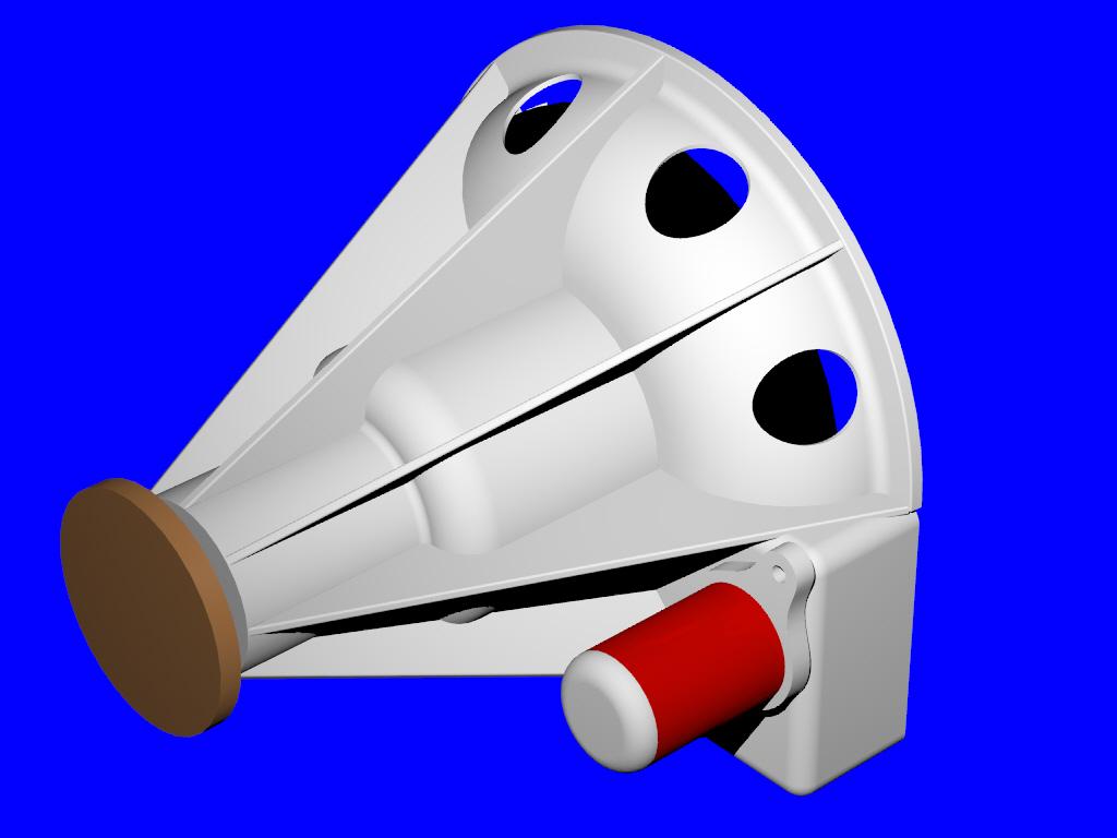
Largest diameter is about 15 inches for the bolt flange.

Here is what I have come up with so far. The flat lower sides
can be used to bolt on your fabricated rubber bushing brackets
of choice. This give a maximum amount of flexibility as it
seems nobody can agree on just how wide they want their rubber
bushings to be. It is rather more complicate inside as various
and assorted ribs are required to provide support for Tracy's
PSRU.

What does everybody think?

Paul Lamar
Paul,
Couldn't you just incorporate the mounting brackets (for the Majority
users)
in such a way that they could be easily removed (cut back) for those
requiring closer mounting points.
I just feel a single piece unit will be stiffer and stronger.
George (down under)
I agree George but there are some other factors going on here.
Mainly pattern issues. It is tough to put efficient beams out
there and still keep the pattern and casting cost in sight.
The bolt on pieces are almost identical to what Perry is using.
These are cheap and easy to make.

Paul Lamar
Paul - I am sure that I could turn the "bowl" for the bell housing on my
lathe
using wood as the pattern material. The other parts could then be
pieced on rather easily. With a bit of draft and planning it looks like
it could be a simple cope and drag sand casting with no fancy
coring. I made aluminum cast wheels for a sports car project about
25 years ago - Vance J
That is the hard way. It only takes me a couple of hours to make
a pattern. Not only that it does it while I sleep :)

The big thing is the .010 accuracy possible with 3D. You will play
hell turning a bowl only .2 inches thick with a constant wall
thickness by hand. The entire lower half of the pattern is
a box. Mainly due to the necessity of mounting the starter.
then you have the vertical walls on each side needed for the
motor mount brackets. Not to mention all the drafts needed on
all the interior reinforcing webs and all the walls. Then you
have fillets on all the junctions between interior webs and
the outer walls. It could take a month of hard work.

Hand made casting patterns in the age of Rhino and 3D machines
are ancient history.

Paul Lamar
david mccandless wrote:
Paul, I'm not getting a picture of the bell housing rhino, could you
send it again please? (Dr Wankel at NSU did it in millimeters, Yamamoto
at Mazda did it in millimeters, What's this inches mumbo jumbo? Yeah, I
know, the shuttle is in inches! Luv your work Paul! Dave McC
I am too old to change, Dave :)

Paul Lamar
david mccandless wrote:
Welcome back Paul n All, ref the bell housing, I would like to see a
ledge or shoulder or maybe even a notch like Jerry's socket MM cast in
to the mount area so that the loads are not carried by the bolts in
shear. The bolts would only be seeing tension loads; down the years I've
noticed that engine mounts subject to vibration, like lord type mounts
often fail around the thread area when the bolts were in shear. This was
very obvious in VW buggy performance applications. FWIW, If I had a
mount as depicted in the rhino rendering, I would consider putting it on
a 'Schertz' beam. Early days yet though, and I love the concept of the
composite type mount/redrive/bellhousing. Dave McC
Good idea Dave.
I think we can do something like that. The motor mount bracket mounting
surfaces on each side of the bell housing must be faced off anyway so a
small shoulder would not hurt. I'll just add a bit of meat to accommodate
that machining step. (Pardon the pun)

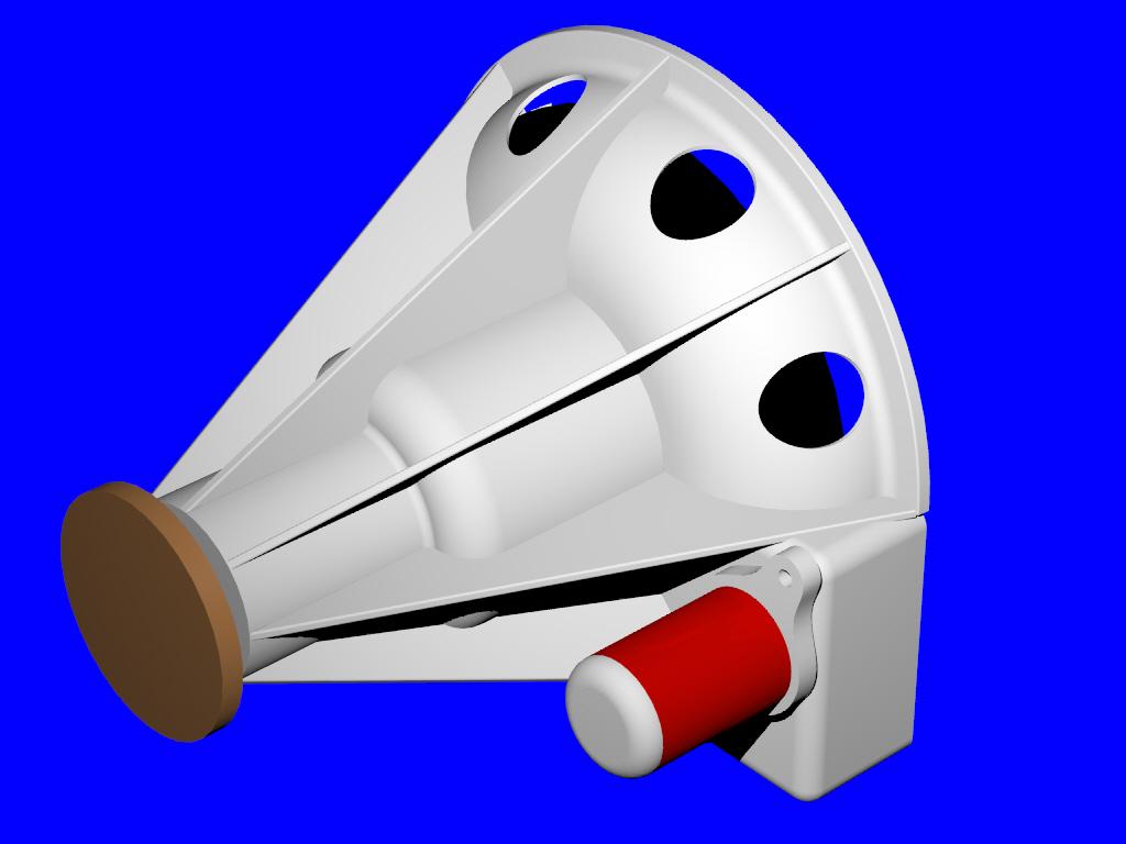
Here is the rendering again for the new guys.

Paul Lamar

The AirCraft Rotary Engine NewsLetter.  Powered by Linux.
ACRE NL web site. http://home.earthlink.net/~rotaryeng/
Copyright 1998-2002 All world wide rights reserved.