Royce,
      On the 2 rotor engines, the rotors are cooled by spraying oil inside
of
the rotor. Will there be a similar cooling means for the single rotor and
if
so how  will it be done? If it is eliminated, will this compromise the
reliability of the engine?

Thanks.

Wally
Wally the rotor cooling oil spray will still be used. The jet will be
relocated to
the e-shaft between the rear end housing and the rotor. Remember the rotor is
being
geared from the front stationary gear.
Royce
Royce,
      Thanks for the reply to my question.

Could you send me a sketch of who this single rotor and e-shaft will go
together?
Do you mean "How" it will go together?
If so, it is like the 2 rotor minus the center housing, one rotor, and rotor housing.
I have an engine that I got but it was in a basket so I really have no idea of
how it will go back together.
A real basket case huh?
I have the capability of doing the machining of the shaft but I have been
waiting for someone to help out with a drawing to get me started.

Hope you or someone else can help out here.

Thanks.

Wally
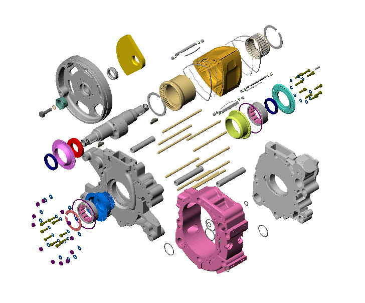
Wally we are attatching an exploded view of the Midwest single rotor for you to feast your eyes
on.
Understand that it is "not" a cut down mazda as ours will be. It does though give you a good idea
of how a single rotor will look.
They use roller bearings and a nut on both ends of the e-shaft. We will retain the bolt and same
setup of the mazda on the accessory end. and the nut on the output end. They also do not taper the
shaft, but we will retain that on the output hub. (very strong joint) Their housing are shaped
differently than the Mazda. It is also a p-port engine and both plugs are even with one another,
not staggered as in the mazda.

They also use  a different output shaft seal setup, and you can see that the counter weights are
both on the opposite side of the ecentric on the shaft. Judging from the combustion chamber shape
they are running this engine opposite from the mazda, but that may also be the way they designed
the combustion chamber and just did it different than mazda. The rotor gear is also retained by
snap rings like most racing mazda's are done. The rear counter weight is on the flywheel, which is
how we will do ours as well. Bruce suggested that plan, so the weight will be less, since it is on
a longer lever. (gotta cut all the weight we can) We know that GM balances their external balanced
engines with this weight on the flywheel/flexplate. It's not really clear in this view how they
control shaft endplay, but the green ring on the front bearing appears to be similiar to the
mazda, so they probably control the endplay much the same way.  They use the rear gear for
phasing, just the opposite of what we will do. (rear, meaning the flywheel end. ) You can see many
similarities  to the mazda, I think they are licensed just as mazda is. (Wankle engine design)
The rotor appears to be wider than the mazda, but that may just be the drawing. It is setup much
like the mazda, seal wise, but I don't see any oil seal rings, just combustion (compression)
rings.. This view doesn't show a corner seal either. (another pic I have of the engine does
though, but not oil seal rings??) Not really sure but the apex seals appear to be "3" piece?
[Image]

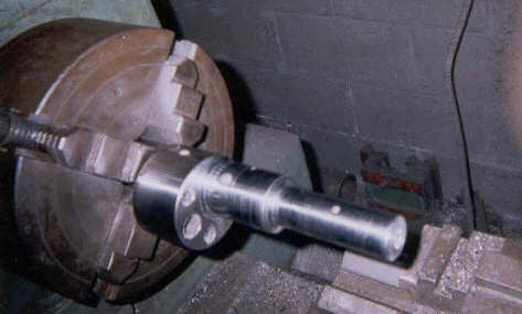
The next pic is the single rotor shaft still in the lathe. It is now cut to length. The  oil grove
on the front journal has not been cut yet, neither has the shaft been drilled and tapped for the
pulley bolt, and it still has to have the oil spray hole plugged in the front main journal, and
the oil spray jet hole drilled and tapped behind the ecentric, cross drilled in the front journal
oil groove, and then finish ground to size.
If you stack the engine together without the rotors you can measure the endplay between the front
and rear gears, and the ecentrics on the e-shaft.
The single rotor engine should have that much endplay when the shaft is cut and installed with the
front and rear housings with gears, and "one" rotor housing.
To establish the single rotor e-shaft length, measure the rotor housing thickness, ( 70mm for the
A's, and 80mm for the B's) plus the center housing thickness. Subtract that amount from the length
of the shaft.
Cut the shaft to the same diameter as the front main journal ( if you are retaining the nut and
rear counterweight design). Remember not to cut it to the exact diameter since you should finish
it to the final diameter by grinding on a crankshaft grinder. Also when you remove the shaft from
the lathe and install it in another machine it will not be aligned just as it was in the lathe, so
do all your machining while it is still in the lathe, and then the crank grinder can center it to
finish grind the journal, and the pulley extension. (snout?)
We just took the length of the front main journal and the pulley extension, and added that to the
front of the ecentric for our length. The end play between the gears is only .001 or so.  This
gives you the same crush on the thrust collar as the factory uses, so your shaft endplay can be
set.  The more of the factory design you use, the less you have to redisign and not kow if it will
work.
Hope this helps you to understand the single rotor a little better.
Royce

[Image]
The AirCraft Rotary Engine NewsLetter.  Powered by Linux.
ACRE NL web site. http://home.earthlink.net/~rotaryeng/
Copyright 1998-2002 All world wide rights reserved.