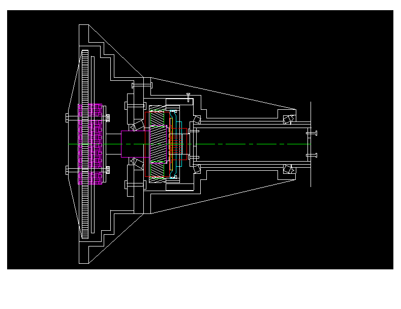
George Lendich wrote:

Paul,
Welcome back - have a good break?

I've taken notice of your postings of the Ross PSRU, in relation to the new bell-housing.
You mention.2" for housing thickness except for the bearing area (what do you recommend for the
bearing area) i.e. width of bearing thickness or a little thicker ?
.25 or .3 should be about right.
Now in relation to the shaft, I pulled out some .2" (5.1mm) mild steel tube I had for another
job - it looked mighty thick. Do you think 3" by .2" mild steel would be sufficient for the shaft?
If you calculate the torsional stress you get a ridiculously thin tube so .2 wall
will not add that much weight for a six inch long shaft. Lets see. The  shaft
will weigh about 3.4 pounds at .2 inches thick roughly. So you might
get out a pound and a half. Hardly worth the risk for such an important
part.
The reason I ask is that I want to do some welding to the shaft and I don't want the problem of
hardening (due to carbon content) and then the need to anneal it !

If I had to go to Chrome Molley - perhaps it could be thinner, but that's harder to get !?
I would not weld on it. If you use a flange with a wide part and low temp braze it
or silver solder it to the tube you will affect the properties of the tube less.
At 800 foot pounds of torque the shear stress in the sweat brazed joint will be low.
If it is two inches long and 3 inches in diameter the contact area will be 18.8 square inches.

800 foot pounds prop torque or 9600 inch pounds divided by 3 inches is a shear
load of 3200 pounds. Divided by 18.8 square inches contact area is only 170 psi.
If it were not for the heat you could epoxy the flange on. Unlike a weld
the shear stress is evenly distributed through out the contact area
What thickness did Ross use ?
My guess is .125 or less.
Again on shaft what do you recommend for length - I notice Tracy tries to get max length for the
reasons he mentioned (on his web site), but didn't recommend a particular length.
I'm thinking approx 6" from outside bearings?
That is about right at 600 foot pounds of prop gyro torque it is a  bearing
radial load of about 1200 pounds apiece. They don't see that load all the
time. Just when you are doing aerobatics or stalling the airplane.
Half that for a wood prop.
The rest of the time they are taking a thrust load of up to
1000 pounds for both or 500 pounds each.
I've attached a drawing of the recommended firewall mounting points for the Vision, I guess you
would recommend the tri - strut engine mount arrangement - yes !?
If yes, would one central mounting suffice for the two struts or is there some critical angle to
consider and would that angle be too wide ?

The recommended Thrust line is -ve 4" below the WL 0 my drawing shows -ve 2.2" to just sneak it in
under the cowling, but it may have to be a little lower ( I mention this for Vision Builders on
this discussion group).

BTW I have also been working on Dampers and lean to my third design (on top) and after relooking
at Tracy's design, I think it must be similar - do you think so? I gone away from Don's Damper
because of RPM limitations when using 2.85 :1 ratio PSRU i.e. over 7,000
RPMs, although I haven't changed my drawing yet!
George (down under)
The AirCraft Rotary Engine NewsLetter.  Powered by Linux.
ACRE NL web site. http://home.earthlink.net/~rotaryeng/
Copyright 1998-2002 All world wide rights reserved.