Russell Kent wrote:
Well, assuming the "100 feet" (above) is the distance from spotlight to wall, and the plane's "location" of
maximum cross-sectional area is 10 feet in front of the wall (plane's rudder at the wall), the area of the
shadowed bricks will be 23% larger than the true maximum cross-sectional area, i.e. correction factor is:
     1 / (( 100 / 90 ) ^ 2) = 0.81.

Do you consider 23% to be an acceptable error factor, Paul?  :-)
Paul Lamar responded:
Wow! That much? Are you sure about that equation?
Pretty certain.
I would think it would also be a function of the actual frontal area.
For example if the the frontal area were disk shaped and one foot in diameter
and it was 10 feet in front of the wall the ray angle would be
6/1080 or  .0055 or .3 degree. If it were one inch in diameter the ray angle
would be a lot less or .5/1080 or .00046 or .022 degree.
If it were zero diameter the area of the shadow would be the same as
the area of the non-existent disk. If it were 10 feet in diameter?
If it were 100 feet in diameter? 1000 feet in diameter?
Well, the distortion that the shape introduces is really not the shape's effect, but rather the brick wall's.
See, to be completely accurate, the brick wall should be shaped like a portion of the surface of a sphere, with
the center at the light source.  I made the engineering shortcut of assuming the wall was so shaped and ignored
the error introduced by that assumption (since the wall would in reality be planar).
Obviously it is also a function of the shape. If you have a long
skinny shape such as a wing the wing span shadow would obviously
be a lot longer than the thickness variation.
Again, that's the fault of the wall and not the wing's.  If the shadow wall were actually a bull ring wall, and
the spot light were in the center of the ring, then the wing's shadow would not be distorted.

The shadow area problem is a pure "one-over-r-squared" problem.  A one square foot area of a sphere at distance X
captures the same amout of light from a point source as a four square foot area of a sphere captures at distance
2X.  In my previous example, the light that the plane captures at distance 90ft is the same as the shadow at
distance 100ft.  Measure the area of the shadow and then computationally determine the area of the plane based on
the distance ratio.

Russell Kent
I agree that a spherical shaped wall would be better.

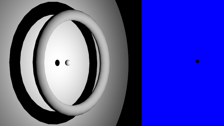
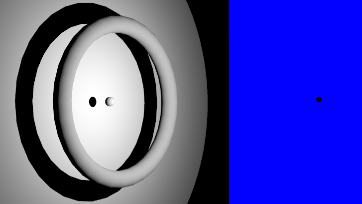
Here is a sphere and a torus in front of a flat wall.
The black spot on the right represents the point source spot light.
The distance to the spot light from the wall is 100 feet
and the sphere and the torus are 10 feet in front of the wall.
As you can see, for the relatively small objects the area error is
minimal and much worse for very large objects. I used a torus instead
of a disk or sphere as you would not be able to see the shadow of the
small sphere.

Therefor I think your equation is wrong. Probably missing some parameters.

We have used this technique many times in the past to measure the frontal area
of race cars and it works well with very little error.

Paul Lamar

The AirCraft Rotary Engine NewsLetter.  Powered by Linux.
ACRE NL web site. http://home.earthlink.net/~rotaryeng/
Copyright 1998-2002 All world wide rights reserved.