Welcome Back Paul;
Looks like the family reunion was a smashing success since you extended your
stay. The guys are not going to like this, but this time I honestly welcomed
the few days the Newsletter was shut down as it gave me a chance to play "Catch-
Up" since I was pretty far behind on it due to a 3 mos, 11.4 lb Grandson's 1
week visit :) It's amazing how such a tiny payload can take over
everything.......So I'll start by answering some of my mail.

Mr. Ed Anderson C.T.P. for ACRE, wrote:
Butch, Paul
    I can not recall - does the LAEV hub flange require the "Bushings" that
are pressed into the SAE2 bolt holes to accommodate the 3/8" prop bolts?
The reason I ask is mine would have to be pressed out of the Ross prop
flange if they are not used by the hub flange.  Also, has the method of
attachment of the electrical strip bushings  to the back plate  resolved?
********************************************************************************

Yes Ed, the LAEV Flange mates to Tracy's ReDrive Flange which is equipped with
Drive Lugs (See LAEV section attachment)..........But, I need you to measure
and tell me the distance your Lugs extend from the face of your Ross
psru......NO rush, you don't have to yank your Prop off now, this can wait till
you're getting ready for testing the LAEV.

Ed, I believe you're referring to the bonding of the LAEV's Contact Disk Slip
Rings to the Insulator Ring???? If so the answer is NO, I haven't heard any
suggestions on this so I'll be asking again in a separate posting.
********************************************************************************

Mr. Ed Anderson C.T.P. for ACRE, wrote:
requirements before flying with the LAEV  Most are obvious, but some of you
may think of  other pertinent factors that need attention.

    1.  The blades stay attached to the hub {:>) and maintain their
structural integrity (Example:  no sign of undue stress or wear at the hub
attachment point, no cracks in composite near hub, etc)
********************************************************************************
Ed, the Blades will be personally "Scrutinized" by at least three of us, Paul,
Perry & Myself, Prior-During and after each Test cycle. (You are of course
welcomed to join us).......As a matter of fact Ed, we are ahead of you on this
since we are NOT protecting the Leading edge with any tape just to expose the
leading edge seam to further abuse throughout the tests.
********************************************************************************
    2.  The blades have a minimum and maximum pitch mechanical stop such
that the electrical control can not force them past that point.  Minimum
point should ensure sufficient thrust for continued safe flight) (can't
recall if the hub design has such, Butch)
********************************************************************************

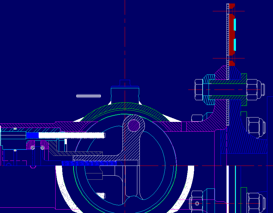
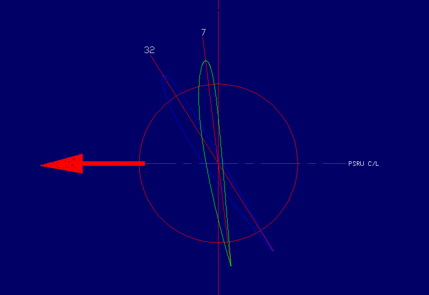
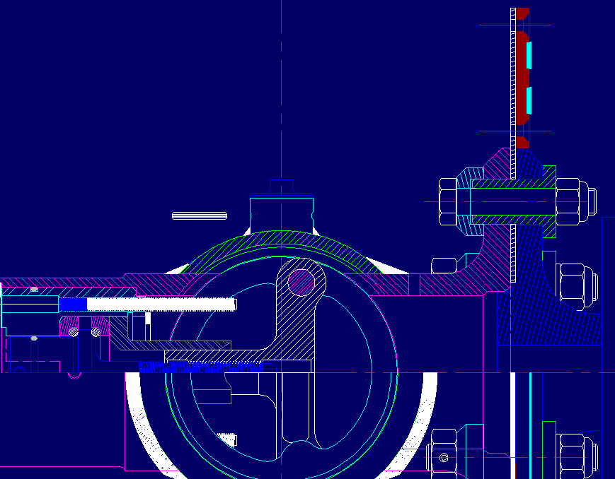
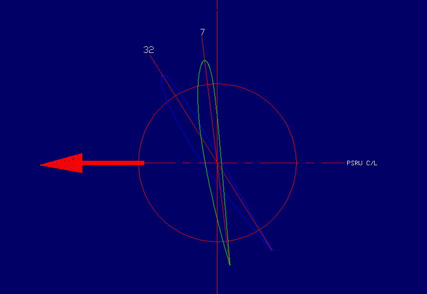
Yes, both Min-Max settings are to Mechanical stops....The Min 7deg stop occurs
in the Blade Shank's slot by the Pin bottoming out (Non adjustable)....The Max
32deg stop is against two (2) adjustable stops which are accessible by simply
removing the Geardrive Motor Cover. In both scenarios the Motor will be turned
off by sensing electrical overload. (Refer to attachments)

The 7deg Min Pitch of the LAEV will ensure the following speeds:

  - 0461rpm = 16.3 MPH (1000 eng rpm IDLE)

  - 1000 "  = 35.3 MPH Level Flight
  - 2000 "  = 70.7  "    "     "
  - 2500 "  = 88.3  "    "     "

Using a 2.17 PSRU, engine rpm @ level flight would be: 2170-4340-5425
respectively.
Doesn't this give a nice warm, fuzzy feeling!!!!
********************************************************************************
    3.  A failure mode analysis of what happens if an internal component
fails.  For example is there any failure mode whereby the two blades would
not be in pitch synchronization/alignment?  If the screw drive fails, does
the blade pitch lock at that setting?
********************************************************************************
Okay, I'll try my best on this one......Take some time and study the LAEV's
mechanism, you will notice the simplicity of the design.........The GearMotor
is connected to the Screw Drive which is connected to the Yoke which is
connected to the Blade Shanks via .375 dia Pins, that's IT!.....
Note:
Screw Drive 100% thread engagement into the Yoke at FULL stroke extension for
MIN pitch (7deg)....
Also note that the Guide Bearing is concentrically supporting the Yoke over 50%
of its stroke.

I'll play Devil's Advocate and cite the worst case scenario:

If the Screw Drive should break the Blades will go to MIN pitch (7deg) due to
aerodynamic loads (Refer to above engine RPM vs Speed), and the Shank will be
held concentric by the Guide Bearing which in turn will hold the Blades in
synchronization.

If a Blade should DEPART, press the PANIC BUTTON decal provided, to EJECT the
other Blade!!!..........Just Kidding :)

Ed, I'm sure there will be additional questions/concerns by not only you but by
other subscribers. But I will assure you, that if we even have the most minute
doubt or suspicion about ANYTHING the LAEV is not flying until it's studied or
resolved -PERIOD-

BTW, You can count on me being there for the test flights......After all
somebody has to push you in the cockpit ;)
********************************************************************************
4. It would be nice if while on the test stand, with the engine running
that the ignition/fuel to one rotor be shut off, so that only one rotor if
providing power.  The engine really vibrates in that mode and could provide
unusual stresses to the prop and hub.  Not that I expect anything to happen,
but would be nice to confirm that.

    Any suggestions as to what gyration parameters the prop/hub should be
subjected to while on the test stand?

Any other suggestions would be welcomed

Ed Anderson
Number 4. is a good idea. I'll see if I can arrange that Ed.

I'll let Butch handle the other numbers.

Paul Lamar