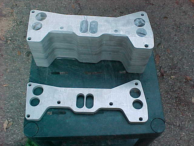
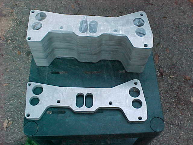
Come to think of it Mike the dwg has allowance for casting shrinkage
so don't take the dimensions for the gospel truth. I checked
the actual casting against a six port flange that I have today and it
looks like there will be no problem porting it out for your
hogged out six port.

Paul Lamar
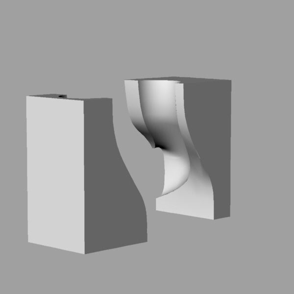
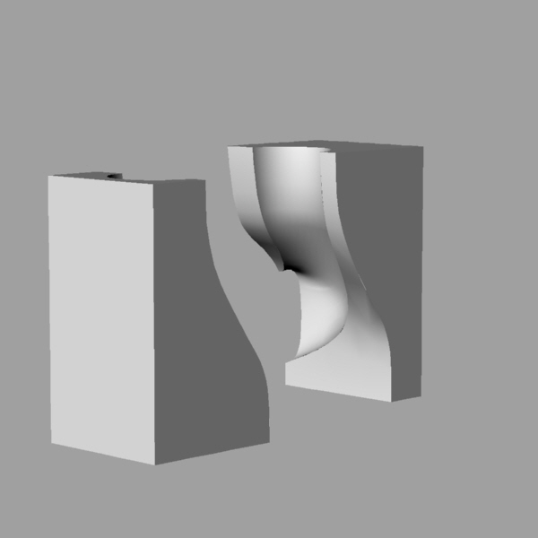
What I'm interested in is getting the maximum radius available on the
inside radius of the runner when I grind out the manifold.  Don't want a
sharp turn as the runner turns toward the port.  I just wanted a profile to
play with.  I should be able to fiddle with the ACAD file and get what I need.
Mike

Mike McGee, RV-4 N996RV, O320-E2G, Hillsboro, OR
13B in gestation mode
OK Mike I'll send the drawing in a day or so. The wall thickness is
pretty thick so I think you will get a fair radius. However this manifold
is designed to clear a turbo so the radius is not as large as it could
be. My guess is on the order of 1 to 1.5 inch center line radius
on average.

If you have the room a three inch center line radius 180 degree tube
or pipe bend would be ideal. The problem centers on forming a transition
from the oval shaped ports to round pipe. Tracy may have some six port
hydra cut flanges left out of a batch we did a few years ago. If you weld
large blocks of aluminum to this flange near the ports and then use a large drill
and die grinder to adapt to the round pipe you might be able to make an
acceptable intake manifold. It will take a pretty high amp tig welder
to accomplish this.

Paul Lamar

The AirCraft Rotary Engine NewsLetter.  Powered by Linux.
ACRE NL web site. http://home.earthlink.net/~rotaryeng/
Copyright 1998-2002 All world wide rights reserved.