Dan Ruggirello wrote:
Hi Paul,
I am interested in the side mount concept for the radiator and decided
to
play around with some 2D CFD code for flow vizualization. Here are
some
results I thought you may like to see. The model for the radiator is
crude
but may give an idea what is happening.

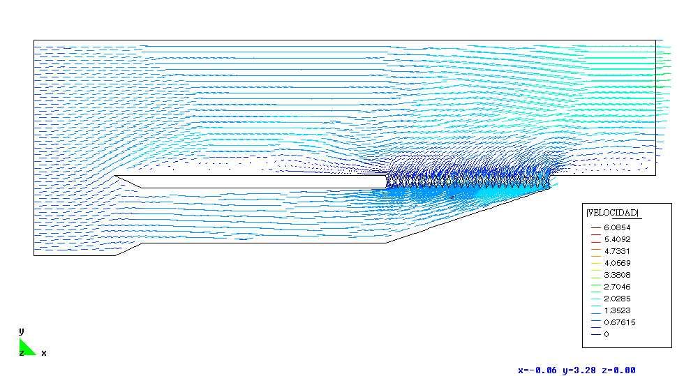
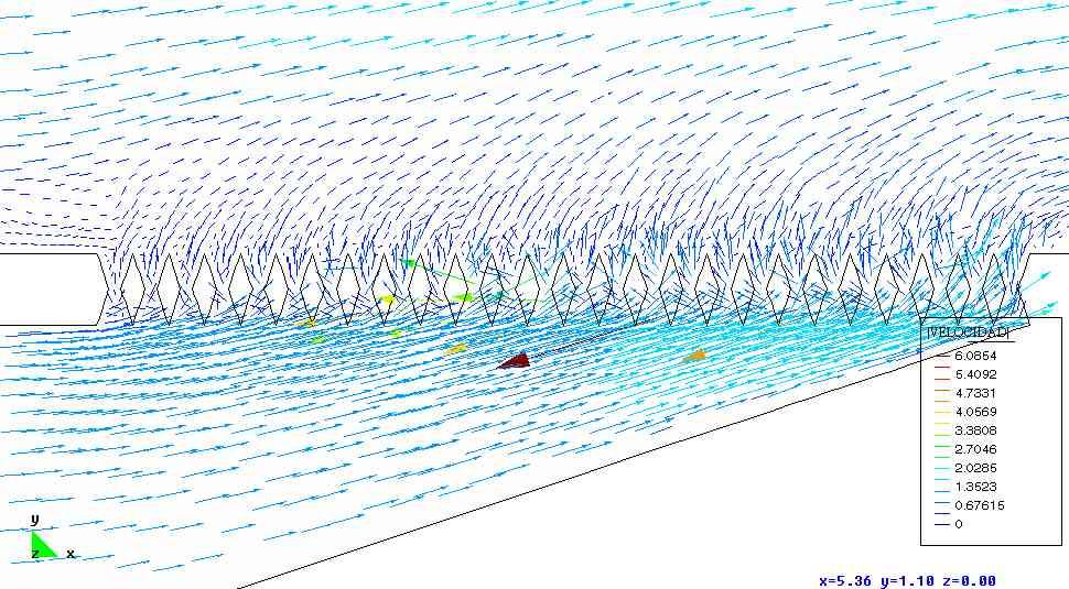
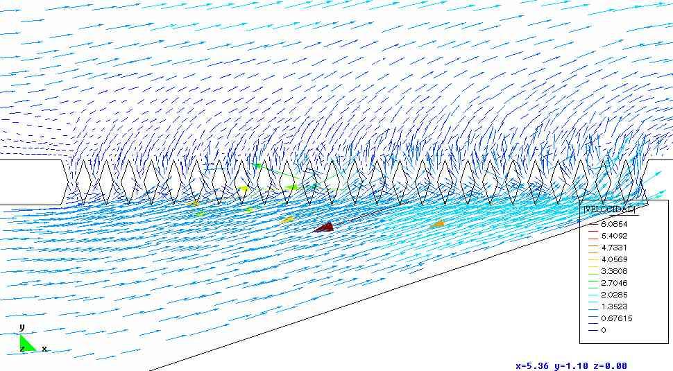
What is interesting is that the flow through the "radiator"
concetrates to
the right. Also, note the flow eddy in the corner of the duct. I
plan on
running a model with a better transition here. What do you think?
How
about the geometry, is it fairly accurate for what you had in mind?
Anything you want to see modeled?

The units are non-dimensional, and the names velocity and pressure are
in
spanish - the code developers are spanish.  I attempted to represent a
velocity of 150mph and duct inlet of 8" by using a Reynolds number of
1E6.
Adios ;-)
Dan Ruggirello

Hey that is real cool looking stuff Dan. Major major break through
here.
What and where did you get this software? Thanks a bunch. Looks like
our years
of talking about this is beginning to get some interest in the air
flow computer
visualization community.

"the flow through the "radiator" concentrates to  the right."
That is exactly what Kays & London maintains and I verified with full
scale test.
That is also the rational for the simple 2D wedge shaped duct

Can you redo the simulation to this configuration? I am mostly
interested
in configuration D without the exit duct but dumping into the free
stream
as you show in your simulations.

Paul Lamar
When we get the inlet duct worked out we can add these cowl flaps.
This will be prime material for the ACRE NL web site with credit to you
of course.
Good work Dan. Thanks a bunch.

Paul Lamar
Here is the ultimate configuration Dan. I am really pleased. This stuff
confirms the research we have been doing on these cooling  ducts for the
last five years. Is this software capably of 3D simulations? Not that
we really need it. I am totally happy with 2D as I think it is
90% of what need for cooling ducts.

Paul Lamar
Dan Ruggirello wrote:
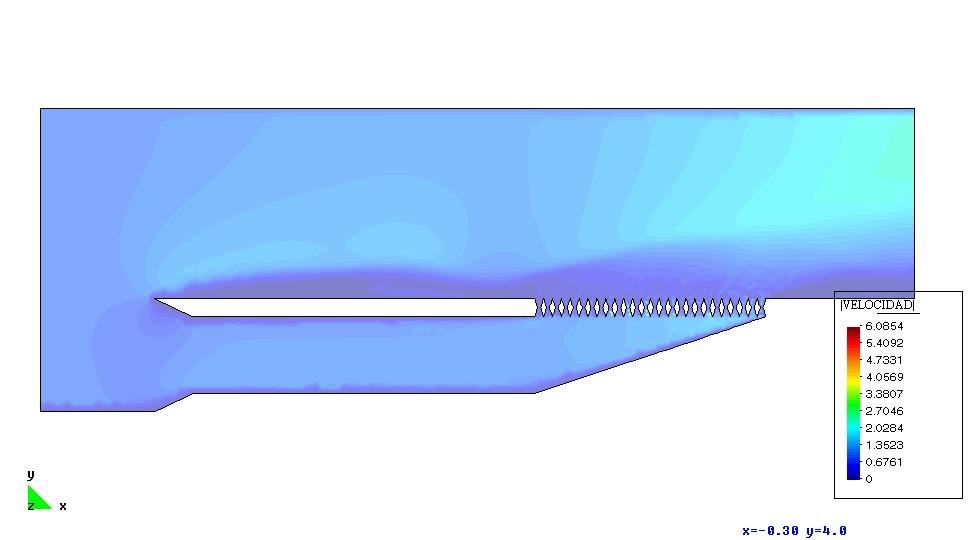
I had a feeling you would like this ;-)  Here are the results for the 2D
wedge.  I made a few more changes from the previous run.  (1) decreased the
duct length in order to increase the area of the approaching air to the left
of the inlet. (2) increased the area downstream of the exit (3) increased
the free stream ceiling  (changes 2 and 3 allow the flow to develop a little
better after exiting the radiator) (4) changed the inlet from a radius to a
ramp (5) increased the number of nodes and elements in the vicinity of the
radiator.

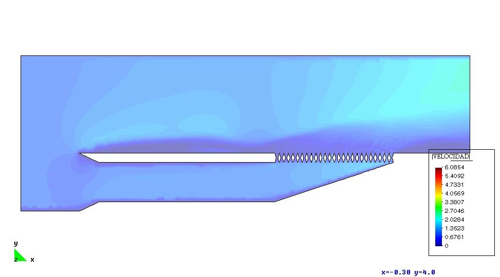
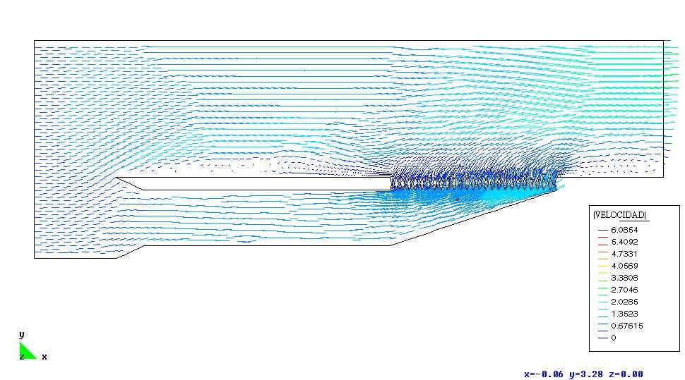
Interesting results.  The flow through the radiator is much more uniform
than the elbow transition from the previous run but velocities still tend to
be somewhat higher to the right.  You can clearly see from the pressure
contour line plot that you have relatively dense contour lines through most
of the radiator vanes compared to the previous run but still denser towards
the right.  You can also see it in the velocity plots.  Also, in the the
previous model you can see that the exhaust stream seems to push the free
stream farthur away than the wedge.  I suspect this has more to do with the
higher exhaust velocity towards the right of the radiator in the previous
model than with the model changes 2 and 3 above.

The wedge seems to act as a venturi of sorts.  You can see the pressure
decrease and velocity increase within the duct as the wedge narrows.  I
suspect adding the inlet diffuser as in your ultimate configuration will
help further equalize the velocity through the radiator.  Maybe I should
model that next?

Another interesting observation from the velocity vector plot, is that you
can see an eddy current just upstream of  the radiator exit on the free
stream side that was shed from the sharp inlet corner. Keep in mind that
this cfd analysis was is in the time domain so I have incremental results
from 100 - 600 seconds.(I only extracted increments of 100s though to save
on post-processing time).  The results I attached are from the last snaphot
in time at 600 s.  What is really cool is you can see the progression of
this eddy current and how it interacts with the radiator exhaust stream if
you animated the incremental results. But the eddy current doesn't change
the flow through the radiator significantly.

The number of nodes in this model was 20600 and it took about an hour to run
on my 1Ghz laptop.   The boundary conditions are a velocity of dimensionless
1 at the left edge , and along the top edge of the model.

I have been searching for inexpensive CFD code for awhile and found this
navier-stokes solver freeware called ADFC which was written by a masters or
phd candidate from spain.  You can find the software at
http://sourceforge.net/projects/adfc/.  A couple caveats though.  (1) It
only runs with a poor quality pre/post processor called GiD
(http://www.gid-usa.com/) which is not free but relatively inexpensive and
(2) the solver manuals and tutorials are in spanish.  The solver and
pre/post software are supposedly capable of 3D solutions, but I havn't
endeavored there yet.

Dan
Too cool Dan. Thanks a bunch.
Here are the three out of the six that best illustrate the situation IMHO.
Can you do the cowl flaps for us next?

Paul Lamar

The AirCraft Rotary Engine NewsLetter.  Powered by Linux.
ACRE NL web site. http://home.earthlink.net/~rotaryeng/
Copyright 1998-2002 All world wide rights reserved.