Dan Ruggirello wrote:

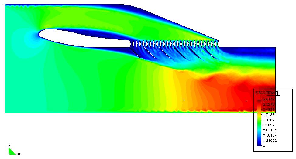
Here are the results for the 2D wedge with inlet diffuser and cowl flaps modeled.  I inverted the
geometry for a bottom exhaust configuration - just easier for me to visualize.  The diffuser inlet
geometry is eyeballed from the 3D model you sent.  Send over any profiles you want to see (IGES).
Do you know typically what the percentage of open area through a radiator is?  The model is about
35% open area.

It looks like the the shape of the diffuser may influence to a degree how the flow gets spread
across the radiator.  For this model, the diffuser looks like it "stalled" creating a low pressure
downstream of the separation point and through the left of the radiator causing low flow here.
One thing I don't quite understand is the diffuser doesn't seem that functional since the velocity
seems fairly uniform through the duct.  I re-checked the Reynolds number and the model should be
approximating ~150 mph flow.  I need to re-check the boundary layer velocity profile variables
that are being used.  I think what may be happening though is that the diffuser transition
geometry is too abrupt for this velocity, or perhaps the radiator open area is not realistic.  A
more gradual and longer diffuser may be what is needed which may mean moving the radiator as
far back as possible.  I don't know, just a thought for now.  What do you think?  Do you have any
emperical data?

Overall though, what are the goals?  Maximize airflow and uniformity through the radiator?

Man, this stuff is fun!  You know, we can also run some models to simulate climb-out angles of
attack.  Would this be useful?

Dan Ruggirello
Dan, looks like the height of the opening is a bit too high. The rule of thumb
is 25% of the rad area. Typical rad would be 20 inches wide by 16  inches
long. A simple wedge opening would therefore be four inches high by 20
inches wide. Or the height of the opening should be about 25% of the length
of the core.  Also the cross sectional area of the duct in front of the
wedge should be constant. That should eliminate the obvious boundary
layer build up on the bottom of the duct as shown in this configuration.

Paul Lamar

The AirCraft Rotary Engine NewsLetter.  Powered by Linux.
ACRE NL web site. http://home.earthlink.net/~rotaryeng/
Copyright 1998-2002 All world wide rights reserved.