Dan Ruggirello wrote:

Paul,
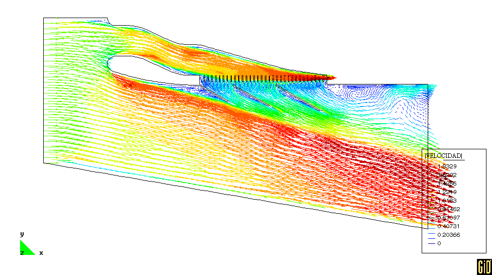
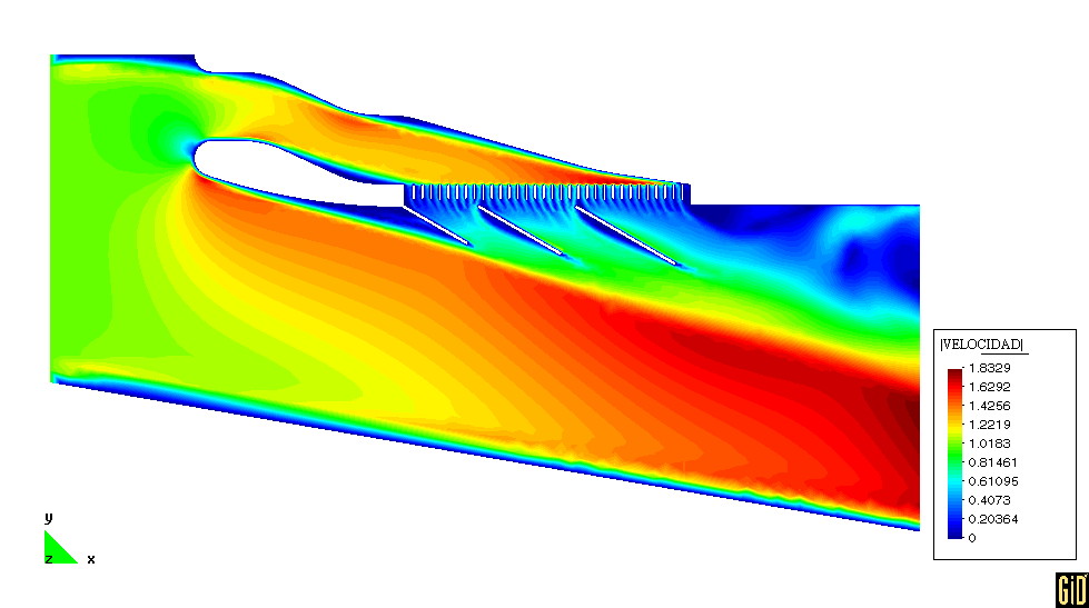
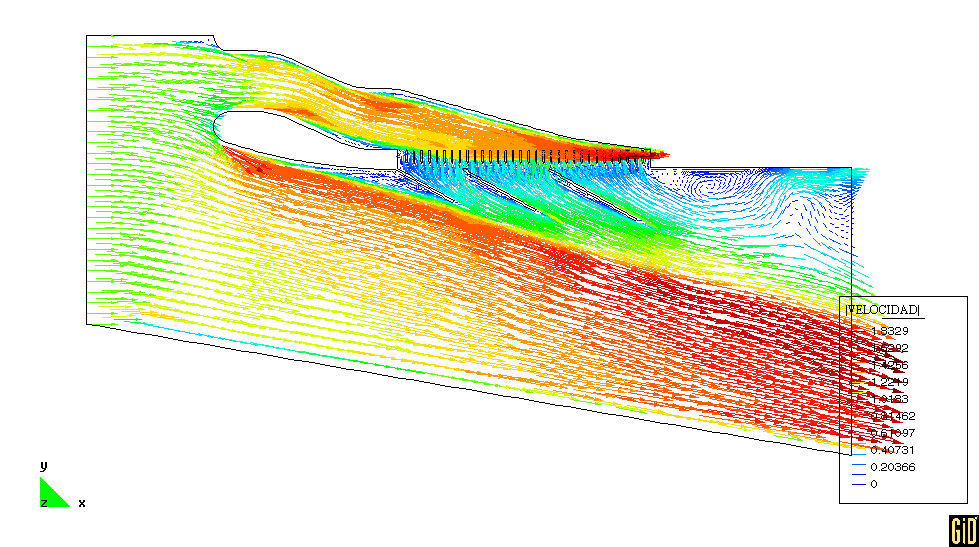
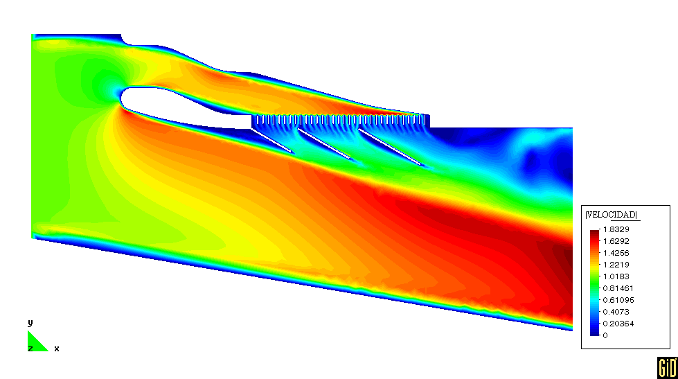
Profile R5 is what I ran last night.  I doubled the radiator vanes and I thought I had an open
area of 1/3 but after I ran the model I rechecked it and found that I mistakenly made it 25%.  I
found that according to the Stewart website
(http://www.stewartcomponents.com/html/tech_support/advanced_cooling_system_basics.asp) radiators
have typically 1/3 open area.  Not sure if this is true for all radiators?  This model took about
5.5 hours to run and has ~41k nodes.

R6 is the profile you sent to run.  The velocities through the duct seem greater than previous
runs, perhaps due to a relatively large open area (89% open area).  In general it looks like
modifying the top of the wedge with a slight downward curve as you did seems to push the velocity
distribution towards the left.  This model took about 1.2 hours to run and has ~25k nodes.

What do you think about an enclosed exhaust vent with the cowl flaps inside?  It may help keep the
exhaust stream closer to the plane thereby reducing drag.

Dan
25% is the bottom limit I would guess. 33% might be slightly higher drag.
I think it is a good idea but hard to implement with a liquid cooling system.
One could also put a butterfly valve in the intake.

IMHO there is something a bit wrong on the velocity data. How can the velocity
in the duct in front of the rad be much much higher than the velocity just
on the other side of the rad. V4_R6c looks more like pressure data.
Velocity through the rad should be a function of the pressure difference
across it.

Paul Lamar

The AirCraft Rotary Engine NewsLetter.  Powered by Linux.
ACRE NL web site. http://home.earthlink.net/~rotaryeng/
Copyright 1998-2002 All world wide rights reserved.