I hate to ask dumb questions about this stuff since all I know about it
is what I've 'read in the papers' (to mis-quote a dead humorist), but
here goes:

First, all the versions so far seem to have more or less parallel walls
on the duct which would not give any pressure recovery. The velocity &
pressure representations both seem to confirm this as there is no
slowing in the duct and no pressure increase.  Shouldn't the duct be
tapered for pressure recovery?
The wedge over the rad takes the place of the classic diffuser. PL
Second, the simulations show an obvious increase in speed & decrease in
pressure above  the pinched trailing end of the duct over the radiator.
 Bernie Kerr has built & tested a duct without the pinched area at the
trailing edge of the duct. It showed equal flow from one end of the
radiator to the other. Are we missing something here?
That's strange.  Kays & London, Kuchemann & Weber, Dan  and me all found
the opposite effect.   PL
Third, it's been well documented on air cooled planes that the lip at
the bottom of the firewall (right edge of the radiator in these images)
should be given a generous radius to help the air transition from
downward to rearward direction. Wouldn't it be worthwhile to move the
trailing (right) edge of the radiator up a few inches & radius the
'firewall'  corner?

Fourth, if you rotate these images 180 degrees, they look like the
airspeed/pressure representations of the top of a stalled wing. It looks
like a very high drag & even inverse lift situation to my untrained eye.
 The air flowing past the exit duct seems to be working like a venturi
creating a large low pressure area below & behind the duct. Shouldn't
the exit air be re-accelerated by the duct to slipstream speed to reduce
this drag?

'I am only an egg', so please enlighten me.

Charlie England
I had the same thoughts as Charlie but may have part of the answer.  Bernie
has done a lot of pressure & velocity measuring on his plane and came to the
conclusion that in the case of conventional inlets (holes in cowl on either
side of the prop spinner), practically all of the diffusion is *external*
and almost zero was taking place in the duct.  That is what led him to his
"open chamber" plenum for the oil cooler & rad.

Paul Lamar proposed the possibility of external diffusion and I think he was
right.  This would explain why Finn Lassen's cooling system works OK.  He
has absolutely no ducting at all, just a hole into a sharp cornered box in
front of the rads.  If it were not for external diffusion, he would have
burned up years ago.

This factor is very significant in choosing cooling inlet location.  Note
that the external diffusion is only available in *very* few locations on the
airplane. This is why I'm sticking to the stock cooling inlets on my RV-8.

Tracy Crook
tcrook@rotaryaviation.com
www.rotaryaviation.com
External diffusion happens anywhere flow into the duct is restricted.

If the P51 type duct is on the aft end of the airplane where the boundary layer
has had considerably time to build up and there is insufficient
distance between duct opening and skin surface the airflow will
merely be diverted around the opening. This in effect is what happens
to the NACA duct when used with a flow restriction like a radiator
even if located where the boundary layer is thin. If the duct is
out of the boundary layer and the flow into the duct is restricted,
say by too thick of a rad, external diffusion will also take place.

Once the flow enters the duct and the rad is not perpendicular to the
axis of the duct the wedge shaped effect comes into play. The air pressure
will build at the back of the duct due to the inertia of the air.
If the duct is NOT a wedge shape more or less most of the air will try to
flow through the rad closest to the back of the duct. The part of the rad
nearest the front will have less flow.

If the rad is perpendicular to the flow and a bell shape is not used there
will be separation of the flow on the duct walls and most of the air will
impact the center of the rad with a consequently loss of rad flow
around the edges. If the duct is not about 2-1/2 times longer
than the max dimension on the rad a small opening (25% to 30%) can not be used.
In that case a larger and larger opening as the duct gets shorter and shorter
will be required. The limit to this is no duct at all with just the rad stuck
out into the air stream perpendicular to the flow like a WW I fighter plane.
Any air that cannot flow through the rad for what ever reason such as
an object placed too close behind the rad will cause external diffusion
and the air will be diverted around the rad with high cooling drag.

Not however as high as intuition and flat plate drag theory would have
you believe. That was what I was referring to when I said external
diffusion reduces the drag. The WW II Corsair cowl is a good example.
The Corsair was no faster when a spinner was tried because of external
diffusion. Later radial engines were made with longer crank cases and
a longer internal  bell shaped radial engine cowl could then be employed with a
reduction in cooling drag over the Corsair configuration. These had a smaller
diameter opening of less area. The Lockheed P2V and late versions of the
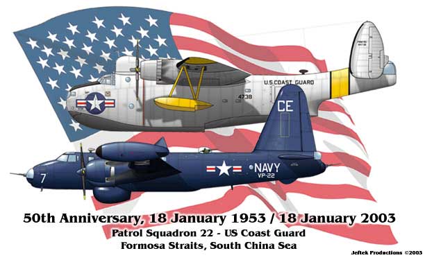
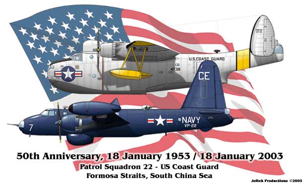
Constellation among others are good examples. Here is a picture that
dramatically illustrates the difference between the old and new
radial engine cowlings.

Bottom line; good design is better than external diffusion.

Paul Lamar

The AirCraft Rotary Engine NewsLetter.  Powered by Linux.
ACRE NL web site. http://home.earthlink.net/~rotaryeng/
Copyright 1998-2002 All world wide rights reserved.