Dan Ruggirello wrote:

I ran a number of cases for Perry's ducting and have found the lack of cooling will be greatly
improved if a deflector is added to divert the strake streamline over the outlet sufficiently to
lower the pressure of the outlet duct.  What is apparent is that the louvers will not add any
significant amount of flow through the radiator because they lie beneath the streamline.  IMHO, it
is more effective to add a full hood over the outlet instead of a deflecting lip because the
turbulence induced by a lip could interfere with the flow at the radiator exit as shown in the
simulations.

I ran a total of 9 simulations, varying the geometry, time steps, boundary conditions etc.
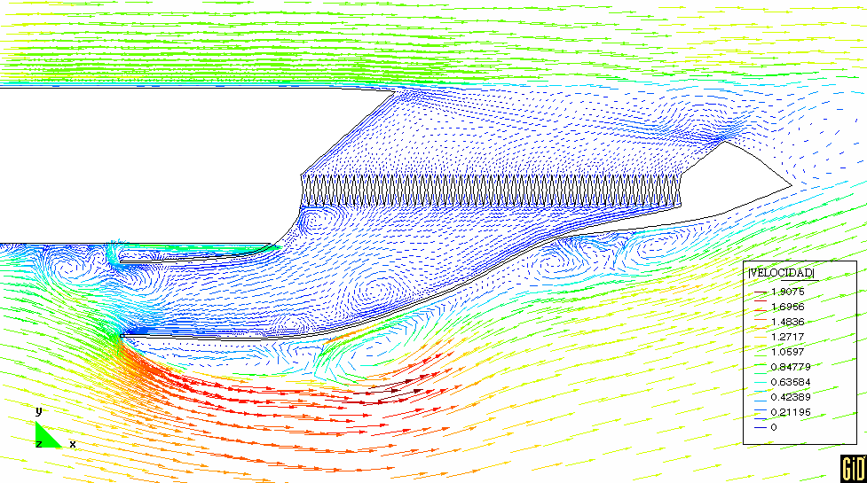
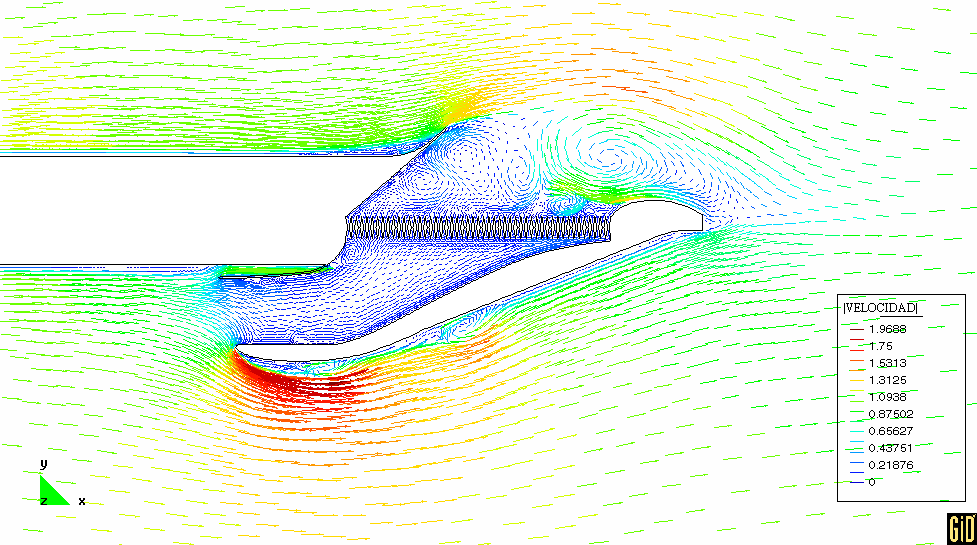
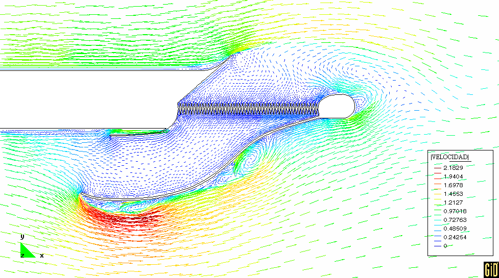
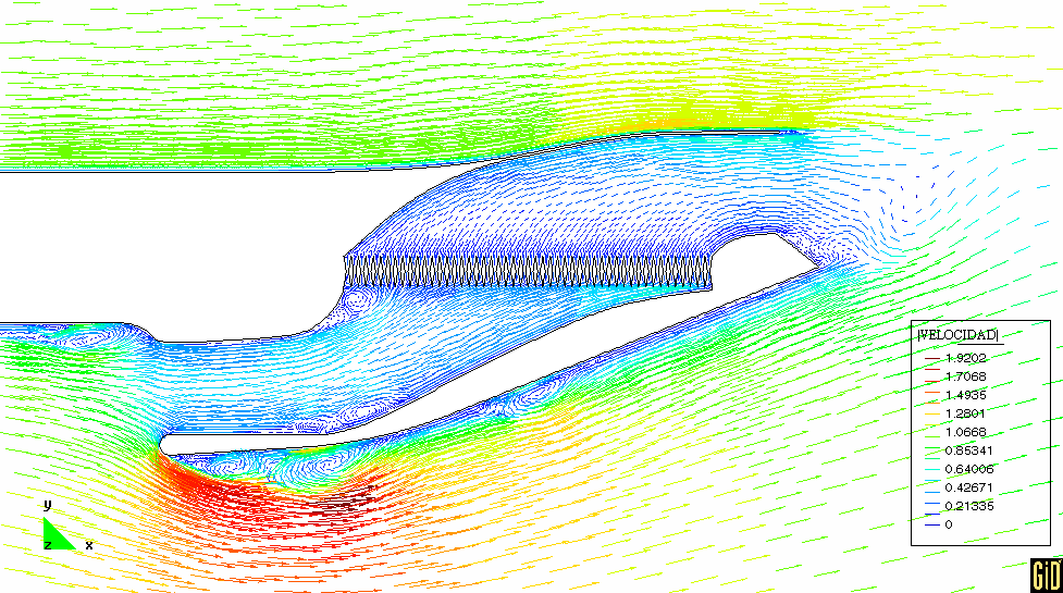
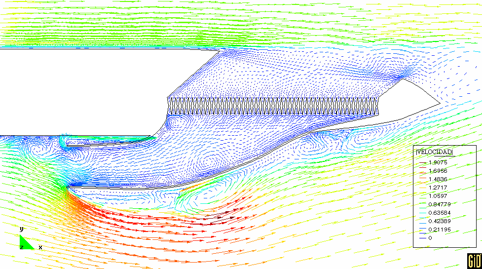
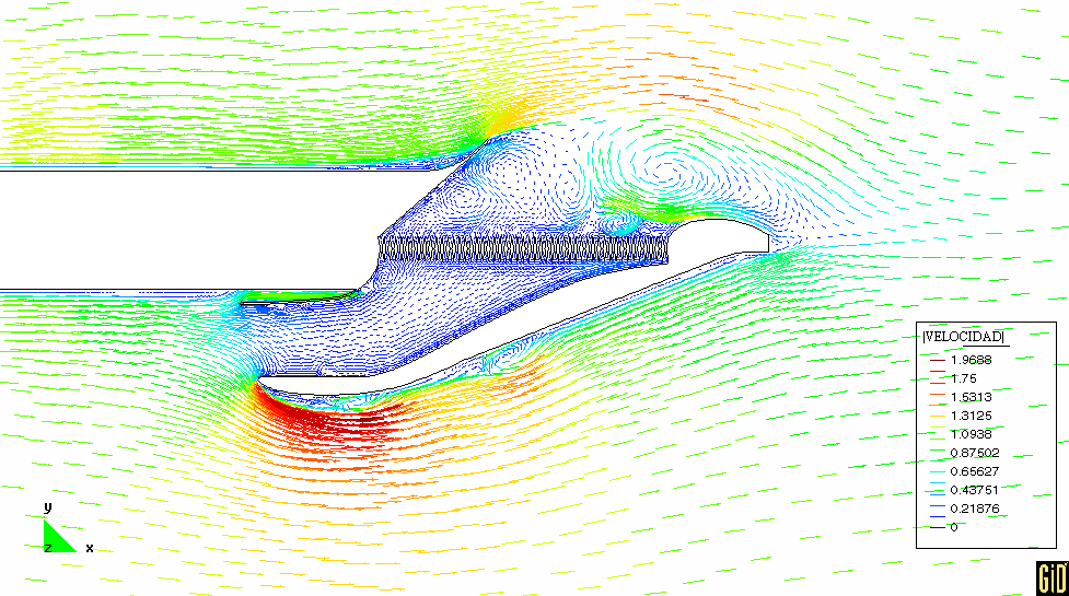
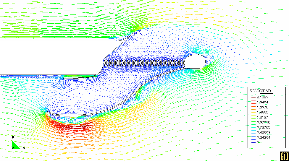
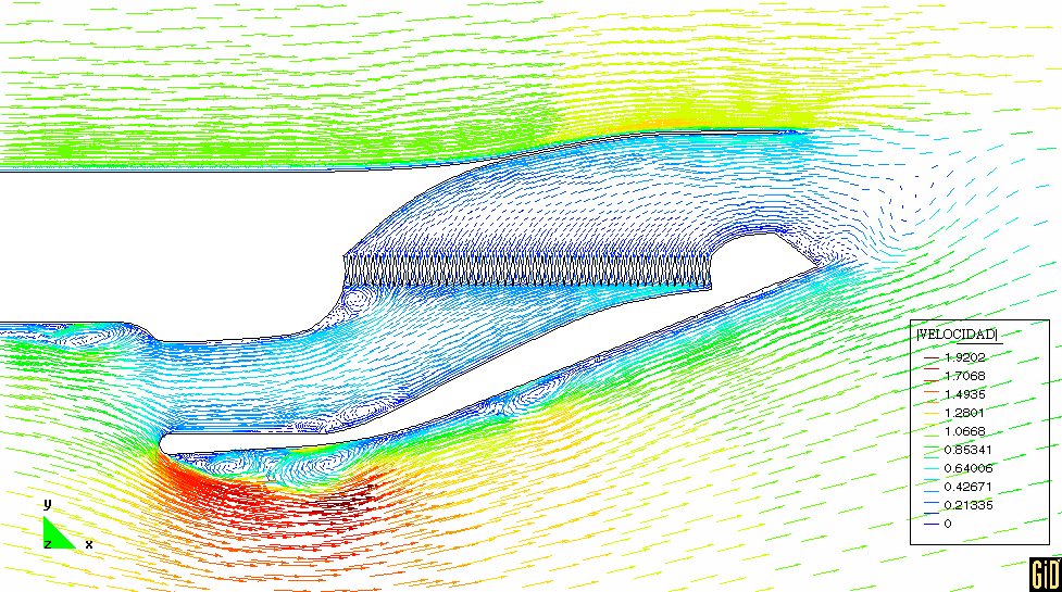
Attached are velocity plots from 4 of the simulations.  In all cases of the simulations I did not
let the run go on long enough for the flow to fully develop into some steady state pattern because
of very long run times, but for a few cases, the runs were long enough to see it approaching some
pattern.

Perry2 is the current configuration.  What is apparent is that there is too much pressure drop
across the radiator causing excessive back pressure in front of the duct inlet.  The flow is
forced to go beneath the duct which induces some boundary layer separation of the bottom of the
strake just upstream of the inlet.  Incidentally, the shape of the top of the inlet lip may help
in these cases, but not sure yet.  For example, if the top of the inlet were attached to the
strake and streamlined as in perry6, you may not get as much boundary layer separation.

The difference between the current configuration (perry2) and the vehicle hood exhaust vents with
louvers that Perry posted is that this exhaust lies in an area where the flow from the top and
bottom of the strake is joining together and there is a downward component to the flow over
the top of the strake nearing the trailing edge.  The exhaust duct on the vehicle however lies in
an area of relative low pressure.  Relative pressures between inlet and outlet are different
between these configurations.

Perry6 shows an exhaust hood that provides uniform exit streamlines and overall increase in flow.
A plot of pressure (not attached) shows a gradual decrease in pressure to the duct outlet.

Perry8 shows a diverting lip over the outlet.  What is obvious is the ensuing turbulence within
the exhaust duct that will effect the flow out of the radiator. However, the louvers would likely
help reduce the influence of the turbulence somewhat.  A higher exit pressure will reduce lip
turbulence which would require increasing inlet area as shown in perry9. Note that exit turbulence
is reduced from perry8. (Instead of increasing the inlet height as in perry9, a better
alternative may be to increase the inlet width.  Keeping the inlet profile as short as possible
could reduce the tendency for strake boundary layer separation upstream of the inlet.)   This lip
configuration would provide better flow than the current configuration.

As you can see, I also played around with the inlet shapes.  A more streamlined bottom inlet lip
could help reduce the distance the flow moves beneath the duct and improve inlet pressures.  The
current configuration of the bottom inlet lip has a slight curve upward towards the strake.  I
think it may be beneficial to increase this a bit more as shown in perry9 (just a hunch for now)
to keep the inlet duct parallel to the flow which may also increase inlet pressure.  Overall
though, it is a game of balancing the inlet pressure.  Too high an inlet pressure may result in
strake boundary layer separation.  Too low an inlet pressure and you don't get enough flow through
the radiator.

I noticed the current configuration profile I was sent has an inlet height about 18% of the
radiator length.  Assuming equal duct and radiator widths, this may be a bit low inlet area to
radiator area.


Dan
Dan I think you have to look at the whole strake in front of the duct
to check the effect of the boundary layer thickness build up.


Paul Lamar

The AirCraft Rotary Engine NewsLetter.  Powered by Linux.
ACRE NL web site. http://home.earthlink.net/~rotaryeng/
Copyright 1998-2002 All world wide rights reserved.