Dan Ruggirello wrote:

Howdy Paul,
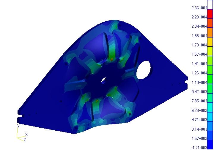
Couldn't resist getting this model going.  Here are some results.  I
constrained the 6 engine
mount locations in XYZ and applied a 360lb load in the Y direction 20
inches away.  These results
are von-Mises stress.   Max stress is really artificial since it is
where the nodes are
constrained and can generally be ignored for the plate.  Max stress I
would estimate at about
16ksi, therefore, lots of low stressed material in this load case as
you can see.
Per MIL-HDBK-5, Ftu=42ksi and Fty=38ksi for 6061-T651 plate.

This model is really just a test to make sure it is working and it
looks good so far.  Next step
could be to somehow constrain the ears appropriately.  Hmmm.


Got any displacement data from the test?

Dan
That is just too COOL Dan!!! Looks like we should taper the ribs.
NEAT!!!

Thanks a bunch for doing this.

Jerry, do you remember how far it deflected when you put the 600 foot
pounds bending load on the motor plate?

Paul Lamar
Sorry Paul,  I have searched my drives and cannot locate the test
results.  I do have a folder which contains photographs of the test.  I
will keep looking.   Jerry
It was .065 as I recall.

Dan, please use .065 deflection at the end of two feet as the deflection
angle.

opp/adj=tan theta or .065/24 or .16 degrees if my math is correct.
Can you use that to work backwards and calculate the max stress?

Paul Lamar
Dan Ruggirello wrote:
Paul,
The deflection I get at 20" is .0687", or .0824" at 24".  The results are
scalable, so .065/.0824*16ksi=12.6ksi max von Mises stress.  But this isn't
an apples to apples comparison.......   I am not pleased with the model
displacement.  I typicaly get an error  <5% and this error is way too high.
I was looking at the model vs the tested configuration and they are not
quite the same.  I modeled up your mmplate4.gif plate - the ribs look
narrower and the bottom pockets taller than the tested configuration which
would mean higher displacement.  Is there a dwg or sketch of what jerry
tested?

Dan
Hey I would settle for .0824. I think the correlation is amazing since
we did not talk about the depth of the pocket or the radius of the
mill used to cut the pockets. The angular deflection is still
inconsequential. 0.0687/20 works out to about .2 degrees.

The deflection shown in the jpg is exaggerated for clarity and
in no way is even near the actual deflection in case the people
not familiar with FEA were wondering.

BTW that is with a heavy metal prop. The gyro torque at one radian
per second yaw or pitch for a carbon or wood prop would be half that.

I am not sure if we have an actual drawing as
the guy that wrote the NC mill program just went on what I gave
him roughly. As I recall we made the ribs one inch wide instead
of whatever was shown on that drawing. Jerry, do we have a drawing
of the actual part Danny programed?

16 ksi is also well within the strength properties of 6061 T6.

If we get a chance we will redesign it slightly to improve
the design based on this work. Great work Dan. I am very pleased.

This is also just an interim solution. What we really need is a
light weight one piece cast aluminum PSRU case with rear loading like
the typical modern automatic transmission.  We also need
a 2.85 gear ratio. If Tracy does not get on the stick
soon there will be others out there breathing down his marketing neck :)

Dan, can that FEA program accommodate some other simultaneously forces
such as what would happen if the gyro torque and the 6G landing
loads were applied to the plate simultaneously? In other
words 900 pound uploads at the apex of both motor mount ears.

Paul Lamar

The AirCraft Rotary Engine NewsLetter.  Powered by Linux.
ACRE NL web site. http://home.earthlink.net/~rotaryeng/
Copyright 1998-2002 All world wide rights reserved.