Dan Ruggirello wrote:

Paul,
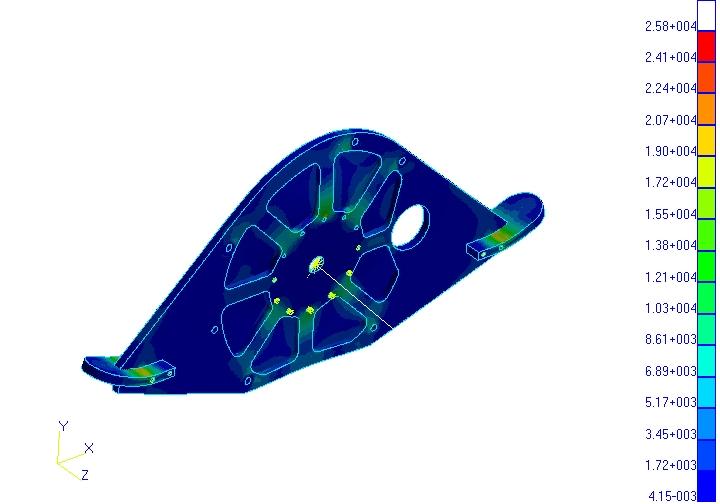
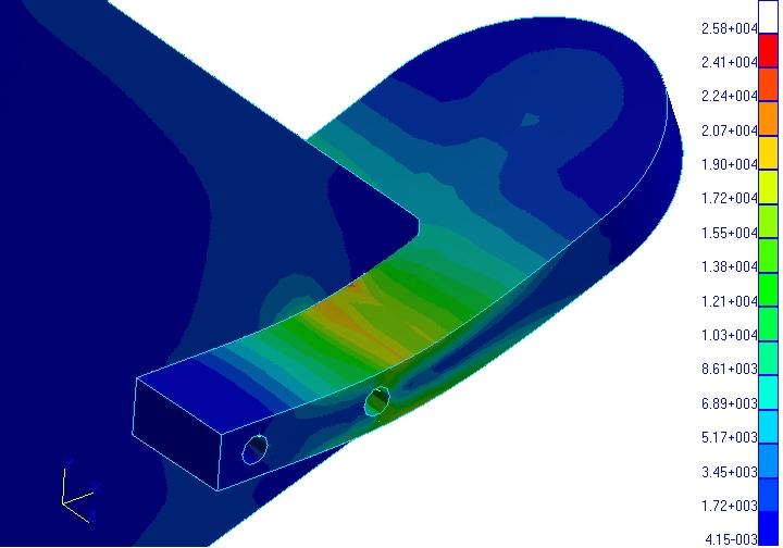
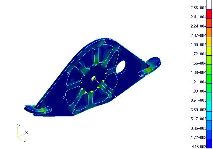
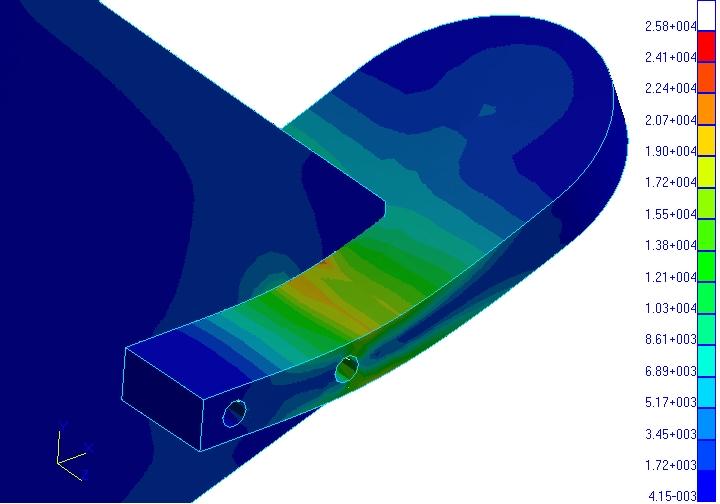
I appled 300 lbs at the tip of a 4"ID/4.188"OD steel beam 24 inches away and 900 lbs +Y on each
ear.  Beam tip displacement in Y is ~0.101".  Max vonMises stress occurs at the ears ~22ksi.

(ref MIL-HDBK-5, Ftu=42ksi and Fty=38ksi for 6061-T651 plate.)
You probably already noticed the inboard fastener on the ears look like they are not loaded.  That
is because I inadvertently modeled each fasteners as tightened down and shear is transfered
through friction, so the outboard fastener would naturally pick up most of the load.  I could
change it to allow full slip, then you would see a force couple on the inboard/outboard
fasteners.  I believe it won't change the stress distribution where the max stress occurs very
much though.


Dan
This is a fun tool you got here Dan.

Not bad for a full power crash landing. I doubt the rest of the structure would
do as well.

Also did you take advantage of the Tab A in Slot B feature out  near the
rubber bushing holders? Does not look like it as there would be
some concentrated compressive loads in the motor plates at those points
just above the rubber bushing holders. Looks like all upload is going through
the outer bolts. Might not be possible in that FEA program.

Don't panic folks. The deflection of the rubber bushing holders is
exaggerated for clarity in the illustration.

Paul Lamar

The AirCraft Rotary Engine NewsLetter.  Powered by Linux.
ACRE NL web site. http://home.earthlink.net/~rotaryeng/
Copyright 1998-2002 All world wide rights reserved.