Bulent Aliev wrote:
Looks like you guys are screwed.. :)
Not at all Bulent. I told you it was exaggerated. Even though this is
not a representation of the actual configuration and it represents
controlled crash conditions (6G's) the stresses are still well with in the
capability of the material and the design. The actual design
uses slots in the motor plate that the rubber bushings holders
slip into. Dan's FEA program was apparently unable to model that.

Paul Lamar
Dan Ruggirello wrote:
It can be modeled.  I just didn't notice the tabs until you pointed them
out.  If you like I can run a model of the ears alone to get a better idea
of the stresses one could expect.  IMHO, if we assume the bolts don't
carry
any loads, the stresses could be a little higher because of the lower
contact area.  But if as you say the 6G loading is already conservative,
then it may not be an issue.

The loads I would be most concerned about are hard landings and the
possible
dynamic implications.  For example, when hitting hard, if you measured the
acceleration and time at the aircraft cg, you would measure a pulse maybe
resembling a 1/2 sine and it would occur over a small duration of time.
The
duration of time depends on stiffness of the gear including tires and mass
of the plane.  If the period of the natural frequency in the direction of
loading (in this case up and down) of the ears or rubber mount with engine
weight is close to the period of the acceleration pulse, you could expect
at
most twice the peak acceleration on the engine of what you measured at the
airplane CG.

Intuitively though, it seems that the engine/ears/rubber mount are much
stiffer than the landing gear and since the engine weight is obviousy less
than the airplane weight, the natural frequency would also be higher.  If
this is the case, then the peak acceleration of the engine would probaby
be
near the peak acceleration of the aircraft cg.  But, something to check.

The $64k question is what is the peak acceleration at the CG of the plane
during a hard landing?  And what constitutes a hard landing?  For landing
gear, Part 23 says to find limit design loads, you can assume a downward
velocity at most 10fps or 6.8mph upon landing.  Or, you could free drop a
plane on gear from a max height of 18.7 inches.

I theororize, if you assume the gear elastically absorbs all the landing
load, and there isn't a damping system in place, you can use energy
equations to find peak acceleration .  That is, if your gear has a
mechanical stop to limit deflection, and the stop is hit during a hard
landing, this theory wouldn't hold.

The following acceleration is calculated using the free drop method.  But,
you could also use velocity instead, or take worse case.

1/2Kx^2 = mgh  (spring energy equal to potential energy)

x = sqrt(2mgh/K)  (solve for displacement)

F = xK = Ksqrt(2mgh/K)   multiply K with x to get peak force

F=ma=Ksqrt(2mgh/K)   definition of force

a = F/m=Ksqrt(2mgh/K)/m

a = sqrt(2Kgh/m)

where
a  = acceleration
K = stiffness of the complete gear
m = mass of the plane
g  = gravitational constant
h  = drop height

So, if you went this route, you would need to find the stiffness K of the
gear.  Looks like an easy thing to do with a simple FEM for some planes
with
spring gear.  Maybe need test data for bungee gear.

But, maybe the 6G loads are already conservative enough.

Dan
It looks like some people panic when they see these apparent deflections :)

You are entirely correct about the stiffness of the entire system affecting
the loading on the motor mount. Vance told me the FAR numbers are around
4.5 G's for landing gears.

I was standing near (75 feet) the upwind end
of the runway at SZP not too long ago talking to a friend with my back
to the runway. Next thing I heard was a whistling sound. I turned around to
see
a dead stick Bonanza strike the runway hard. It bounced back into the air
and achieved
what looked, like from the back, a 45 degree angle of attack. Luckily the
pilot
got it back on the ground and ground looped it just before it was getting
ready to penetrate the fence on the departure end of the runway. The tires
blew
on initial impact and along with the prop left three or more deep groves in
the asphalt.

Upon close examination the cast aluminum motor mounts were broken and
the spar buckled. It looked OK until you got up close.

I think if we stick to 6 G's on this part we will be OK.
One thing about small brackets. If they are over designed it
does not add much overall weight to the aircraft.

If you are going to do just the brackets you might add a fore and aft
thrust load of 500 pounds along with the upload of 900 pounds.
Worst case. Also if you look at the torque it will add and subtract
to the 900 pounds. Lets say 800 pound on one side and 1000 pounds
on the other.

Paul Lamar
-Dan Ruggirello wrote:
Vance, you out there?  Where bouts in the FAR did you see 4.5G's?  I have
been looking into calculating tailwheel loads, and so far, the gear design
loads I found are in Part 23.  Specifically, C23.1, C23.473 , C23.725 and
Appendix C.  The loads basically have to be derived with a test (though they
can be estimated with certain assumptions as I did below).  I am just
looking for more information.

I don't think it is possible that one number is good for all aircraft, but I
could be wrong.  As you can see from the last equation below, acceleration
is a function of mass of the plane, and stiffness of the gear.  Not all
aircraft in the same weight catagory have the same gear stiffness, unless
the stiffness or gear deflection is controlled by an FAR (which wouldn't
apply anyways in experimental planes).  Are they?

Paul -
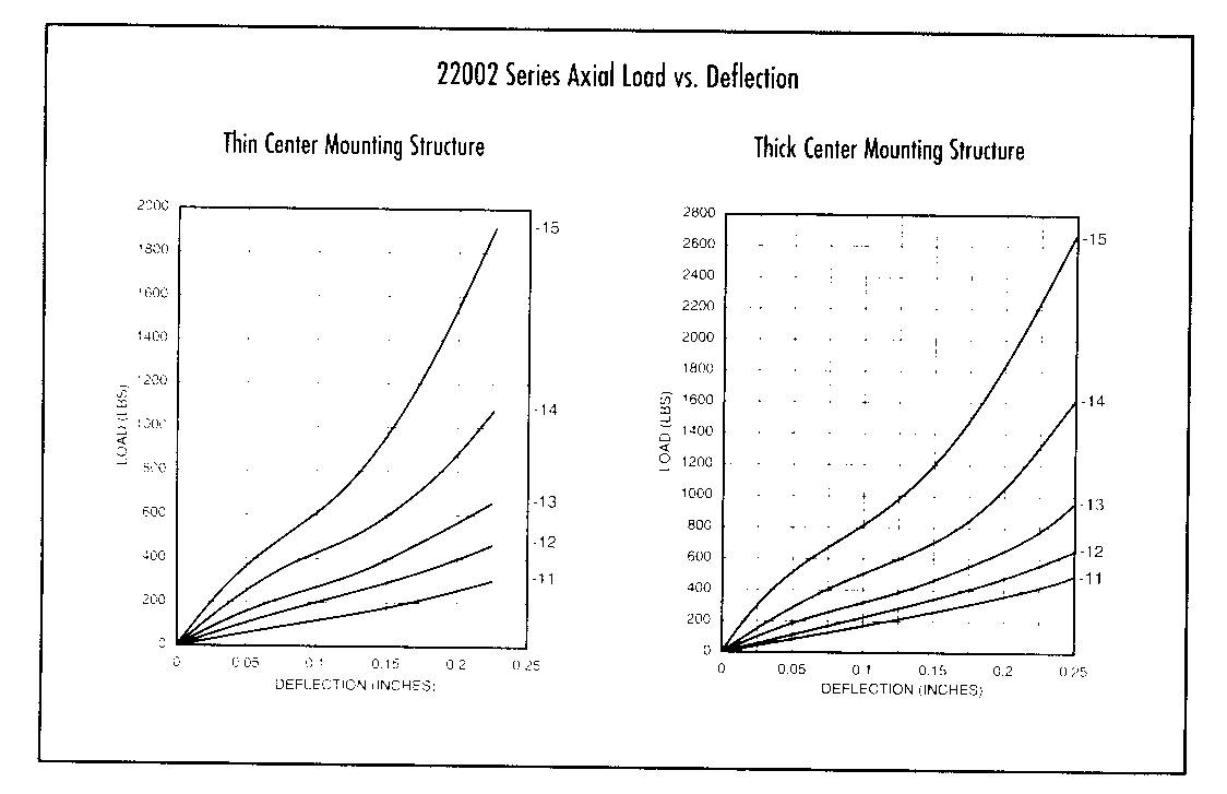
I found the Barry bushing load ratings on-line at their website.  Looks like
the 22002-15 is most common for a 200HP engine?  (Rated static load of 630
lbs per mount).  If so, looks like 6000 lbs/in axial, and 9200 lbs/in radial
should do it.  I'll plug it into the model for vibration runs.

Dan-
I think the 6 G's will cover most airplanes. Now perhaps a Berkut with
a really stiff carbon fiber straight leg might be higher.

I think you want to rate that more like 150 pounds static load or half
the one G load. That will give max vibration isolation. When these things
are subjected to 6 G's of course they bottom out but that only happens
once or twice which will not destroy them. Of course they go non linear
when that happens. 2002-11

Paul Lamar

The AirCraft Rotary Engine NewsLetter.  Powered by Linux.
ACRE NL web site. http://home.earthlink.net/~rotaryeng/
Copyright 1998-2002 All world wide rights reserved.