Paul -
I found the Barry bushing load ratings on-line at their website.  Looks
like
the 22002-15 is most common for a 200HP engine?  (Rated static load of 630
lbs per mount).  If so, looks like 6000 lbs/in axial, and 9200 lbs/in
radial
should do it.  I'll plug it into the model for vibration runs.

Dan-
I think the 6 G's will cover most airplanes. Now perhaps a Berkut with
a really stiff carbon fiber straight leg might be higher.

I think you want to rate that more like 150 pounds static load or half
the one G load. That will give max vibration isolation. When these things
are subjected to 6 G's of course they bottom out but that only happens
once or twice which will not destroy them. Of course they go non linear
when that happens. 2002-11

Paul Lamar
Dan Ruggirello wrote:
OK, the -11 is then 1333 lbs/in axial, and 1666 lbs /in radial and used for
the 2 mount system for a ~300 lb static load.  This is what I'll use for the
spring contants.  Probably not even required to use the mounts in the
dynamics model since the isolators isolate at a low12 Hz but it wouldn't
hurt and actually makes the solution a little cleaner since you don't have
to worry about the rigid body modes.

As far as a 2 barry mount system goes, if the mount in the back of the
engine does not have an isolator, there may be vibration loads transmitted
here during climbs, (the 300 ft-lbs at 2500 rpm?).  Also, this could lower
the natural frequency of the PSRU/prop/MMP.  Not sure what the implications
would be since we don't know what the natural frequency is yet.  (Near 2500
rpm?  6500 rpm? )

I would like to find out more where the 4.5/6G number was from though.  But,
for now, maybe just calculate an acceleration based on energy to see how it
compares?  My mounts are bungee and since I havn't built them yet, I cannot
test them for stiffness.  How about your KIS crusier - got a solid model of
the spring gear handy?  Anyone have a model or drawings of the RV gear legs?
Either one looks stiffer than my bungee gear anyhow and we could use those
as estimates.

I would say that Bonanza landing and the F-18 drop test qualify as hard
landings ;-)  Can't design everything to those loads though 'cause we ain't
Russian!

Dan
The Questair Venture successfully uses the two mount system with a rigid
aft mount. Rigid only in the vertical direction of course. In the horizontal plane
it is entirely free to move around so no forces are transmitted in
that plane.

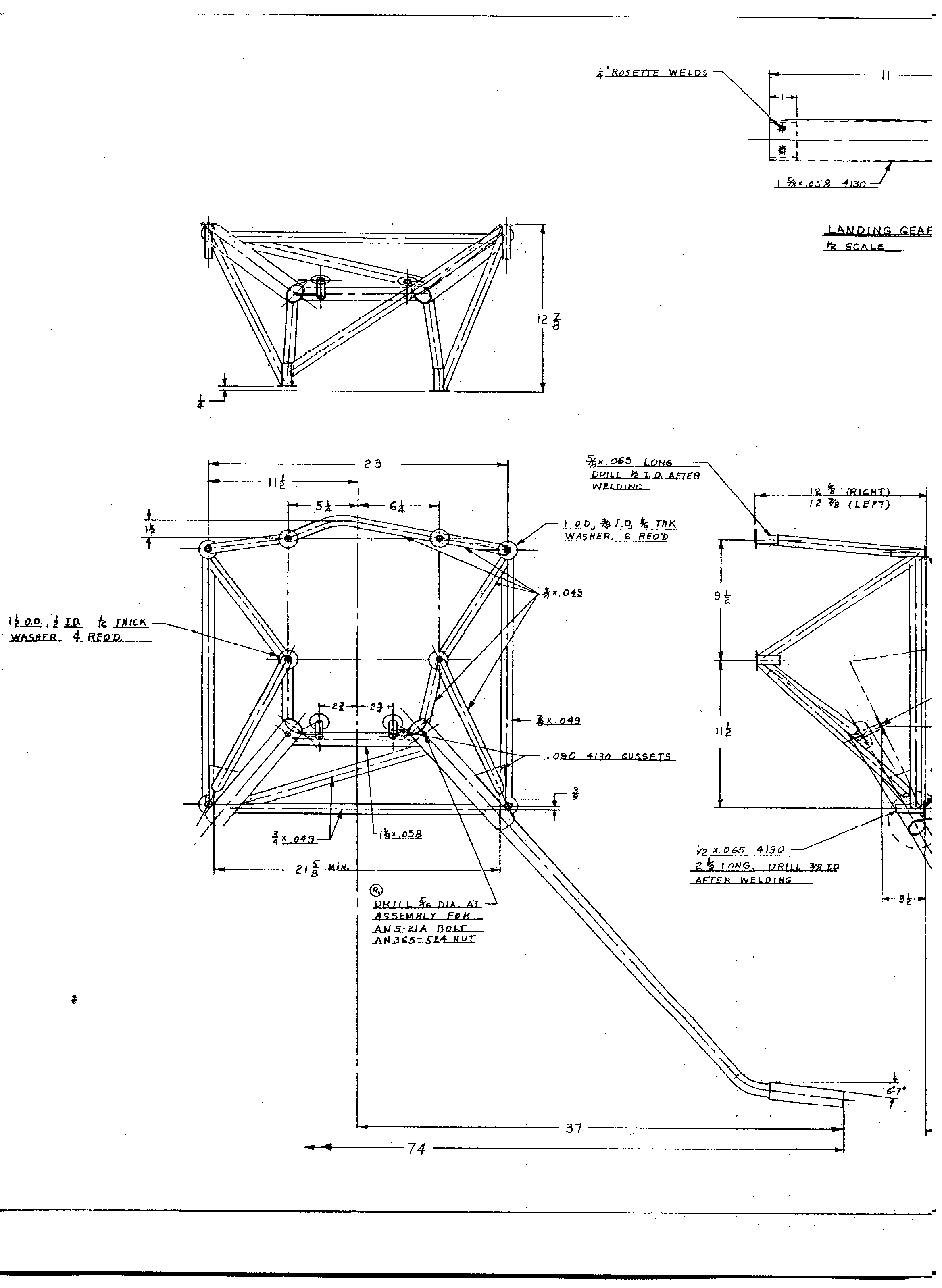
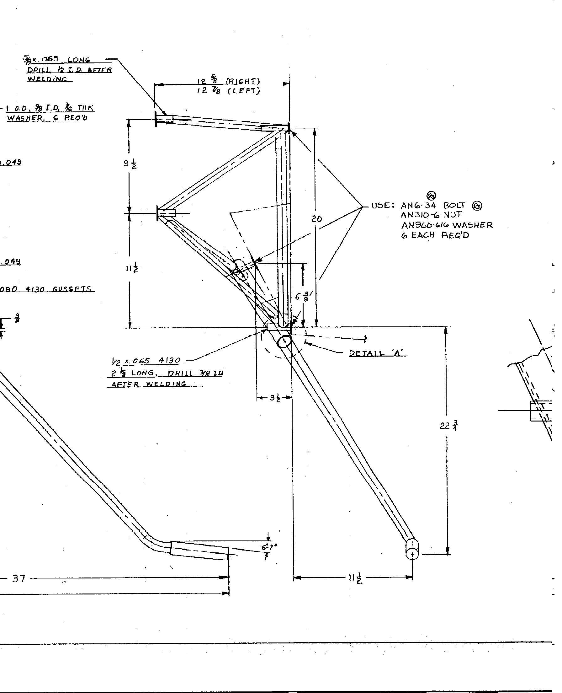
The early RV gear's such as the 3's, 4's and 6TD's were copies of the Tailwind design.
Jerry might have a dwg of the Tailwind in electronic form.

I doubt Vance has a solid model for the KIS Cruiser landing gear  but I could probably
do one in Rhino in a day or too. Any idea Vance what the spring rate at the wheel is
for the main and nose gears? The nose gear uses an automotive shock absorber
with die springs. That of course will bottom out at six G's. I am redesigning
the joint where it connects to the firewall using Barry bushings.
KIS had small automotive shock absorber bushings in that location.

Paul Lamar

The AirCraft Rotary Engine NewsLetter.  Powered by Linux.
ACRE NL web site. http://home.earthlink.net/~rotaryeng/
Copyright 1998-2002 All world wide rights reserved.