Dan Ruggirello wrote:

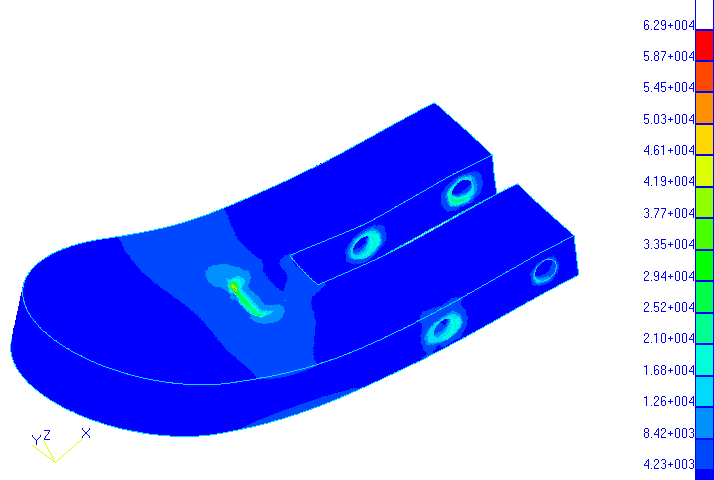
Here are the results for the MM ear.  Applied load was 1000 lbs upload, and a 500 lb thrust load.
I applied the loads distributed on the upper and lower surface of the ear matching the footprint
of the barry bushing.  I fixed half of the upper surface where contact would be made between the
MM plate and ear, and half of the lower surface as a compromise to using contact elements.

The results show a peak stress of 63 ksi, which exceeds the allowables (ref MIL-HDBK-5, Ftu=42ksi
and Fty=38ksi for 6061-T651 plate.
).  BUT, stresses at points in a model are usually artificially high.  Stresses here would be high
regardless though, and what really happens in real life, is the small area under peak stresses
yields slightly anyhow.  Looking slightly away from the peak stress, I would estimate a better
stress level at ~ 35 ksi. Not much of a factor of safety, but if the 6G load is already
conservative.............In addition, these loads are bearing loads, and you would probably find
that the local area under high stress would be marred with local yield, but the ears would
continue to carry full load.

Thanks for all the feedback, it really helps us all out.  I have a few comments on some of the
remarks.

First, the model is not correlated to test, but close.  It is similar to the geometry, but not
exact.  As I said earlier, I usually get within 5% of test values, so this model was off by I
think it was 20% or so and this is not acceptable to me.  So far, statically loaded, the MM looks
OK - test and current model.  However, under vibration we don't know yet.  All that was done was
to find the natural frequencies (or normal modes) of vibration.  Knowing this, it is now possible
to apply the vibration loads to see how the structure responds to these loads.  The response
depends on the normal modes, and the loading magnitude and directions.  I personally don't like
the natural frequencies I see of the plate/psru/prop and the ultimate housing will not have these
plate type modes.

If the plate was vibrated in a way to excite those last two modes, what would happen is it would
resonate and everyone knows what happens when you hit the natural frequency of a paddle, a ball
and a rubberband in between.  Of course it is limited because of the damping (typically, we use a
2 - 5%  damping factor, ( or Q = 10 - 25 magnification) which I would explain later if anyone was
interested) .  So, the consequences are the plate could be stressed (don't know how much - but
probably not enough for failure) and IMHO, more importantly,  there are ramifications for the
PSRU.  Probably more wear on the bearings etc.

Someone may bring up that the PSRU has a dampener inside.  Yes, but I believe it is only active in
torsion - can anyone verify this?  If true, it wouldn't do much about the psru bending and moving
fore and aft with respect to the crankshaft.  The negative effects assume that the loads were
applied at the natural frequencies.  Which leads me to the question - what are typical engine and
prop rpms that you will run continuously?

As far as how the accuracy of the model effects the natural frequency of the plate etc....my
experience has been that it is generally difficult to change the natural frequency of a system.
In other words, because frequency varies as the square root of stiffness (K) divided by mass (M)
you have to have large values of either to influence the frequency. It would be better though to
have a more accurate model - my placement and values of the lumped engine and psru/prop masses
were just wags and I need some better estimates from  builders/flyers.  (I am only on the fuselage
still, so don't have much data yet).  I believe the normal mode values may move around a little,
but you will still see these modes on the plate.

Dan
The AirCraft Rotary Engine NewsLetter.  Powered by Linux.
ACRE NL web site. http://home.earthlink.net/~rotaryeng/
Copyright 1998-2002 All world wide rights reserved.