Fred Osborn wrote:
A problem the single rotor guys have is how to get an oil
dipstick and filler tube set up since we don't have a
intermediate housing. Attached is what I am doing.

I have decided to change to an updated crank angle sensor
which leaves an empty hole in the front cover. It turns out
that the oil filler tube OD is a press fit into the lower
end of the crank angle sensor hole ID. Paul told us that the
oil filler and dipstick tubes were a press fit into the
intermediate housing. Sure enough, a little back and forth
with a rubber mallet and some penetrating oil and out they came.

I cut the filler tube to length, drilled a small vent hole
towards the lower end, smeared JB Weld around the upper end
and beat the filler tube down into the empty crank angle
sensor hole. The front cover was then set bottom up so the
JB Weld would flow down around the tube upper end before it
cured.

For the dipstick I drilled a hole in the filler tube cap and
reamed it to fit the dipstick tube. The upper end of the
dipstick tube was given a heavy coat of JB Weld and inserted
in that hole. Then I drove on a 3/4 " hard urethane foam
washer cut for a tight fit around the tube and into the cap
ID. More epoxy followed by a fitted steel washer followed by
more epoxy.

The dipstick will have to be shortened and remarked. Small
bends in the dipstick together with a chain guard mounted
under the heads of two stationary gear bolts will keep it
from any contact with internal moving parts.

Fred O.
I'm working on a similar but different approach to the oil fill/dip stick
problem.
The problem with the stock location of the fill tube is that it is right
where the intake runners need to come together into the air
regulator/distribution box.

I'm planning on making the distribution box out of fiberglass will use a PVC
1-1/2" trap union (180 degree bend) to loop the inside 1-1/4 runners.  I
will cut an opening in the bottom of the PVC to allow the air to enter from
the air throttle valves.  The PVC will be installed inside of the fiberglass
distribution box.  Their will be two bell shaped inserts made that will
transition the 1-1/2 PVC trap to 1-1/4 pipe size.

I turned down a piece of 1" electrical conduit so that it would fit into the
engine block where the original fill tube use to be.  I then hacked off the
top portion of the original fill tube so that it can be welded to the top of
the electrical conduit.  I enlarged the inside curve of the PVC by removing
some of the PVC material to allow the PVC fitting to wrap around the fill
tube.  This allows the inside runners to begin their curved interconnection
at a point that is tangent to the forward/aft sides of the fill tube. I also
plan to modify the fill tube cap to contain a dip stick.

This is still in the planning/development stage but it looks like this
solution will (1) keep the intake runners at the optimum length  and (2)
keep the intake manifold at a low profile and (3) provide a solution for the
oil fill/oil dipstick problem.

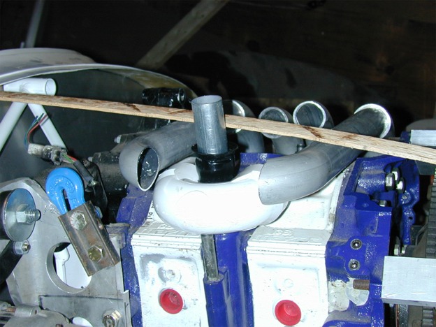
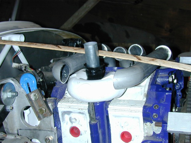
Attached is a picture of the components.  The fiberglass distribution box
(not shown)will be fabricated around the components that you see in the
pictures with the oil fill tube located on the outside of the box.  The
throttle body will be position below the interconnecting intake tubes.  The
new fill tube (electrical conduit) currently extends through the top portion
of the original fill tube.  The conduit will be eventually cut to size and
welded to the upper fill tube body.  The curved wood stick shows the
approximate location of the cowling at the location of the fill tube.

This solution could be fabricated out of aluminum but it is easier for me to
work with fiberglass.  The PVC P-trap provides a smooth media for the air to
flow between the inner runners.
Good idea to make a large flat plenum and put a hole in it for
the oil filler pipe.

Is this a dynamic chamber Del? If the inner runners are connected
together and the outer runners are connected together it is a dynamic
chamber. Dynamic chambers are tuned for half the
RPM otherwise indicated by the length of the runners. In other
words they enhance the HP at 3000 RPM at the expense of the
HP at 6000 RPM. Great for cars. The new RX8 motor is full of them.
Chuck got more useful prop power by doing away with his.

Don't forget to put bell mouths on the ends of the tubes where
they enter the plenum. Very important. Worth 5% or 10 HP at the
200 HP level.

Might be easier to plug up the oil filler neck and weld a bent
steel tube to the oil pan. Aluminum tube if you are using an aluminum pan.

Paul Lamar

The AirCraft Rotary Engine NewsLetter.  Powered by Linux.
ACRE NL web site. http://home.earthlink.net/~rotaryeng/
Copyright 1998-2003 All world wide rights reserved.