William wrote:
Dan,
What information do you need to do an analysis on a different form
of
motor
mount? I designed one using rectangular 4130 steel and bolting to
the
oil
pan bolts. I would be interested in seeing the analysis of this
using
your
tool.

Bill Schertz
Kis Cruiser #4045
To save some time Bill. Dan will need dimensions of the tube and wall
thickness.
A dwg, IGES or DXF file would help.

Paul Lamar
Dan,
The "tape" was to hold the bolts down while putting the assemble
together
before nuts were applied.

I have attached a DWG file. The cross bar is 1"x2" x 0.065" wall 4130
steel
tubing. The ends are 1/2" Aluminum (2024), and I use Barry mounts.

The hole through the bar is for the oil cooler, and has a 4130 steel
tube
welded top and bottom, and then 1/8" plates on the front and back to
make
up
for the missing material.

Bill Schertz
Dan, let me know if you need this converted to an iges.

Paul Lamar
--Dan Ruggirello wrote:
Bill,Paul,
Do you have the fastener locations where the beam is attached to the
block?
Does the block rest on the beam as shown?
Dan
Long oil pan bolts. The engine rests on the beam.

Paul Lamar
Dan Ruggirello wrote:
I appologize about the delay - had to get cracking on the vertical stab.
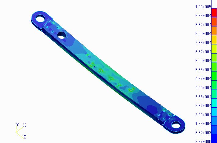
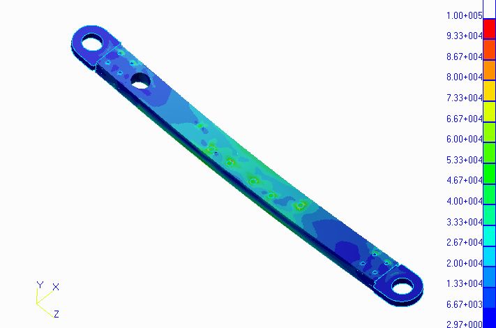
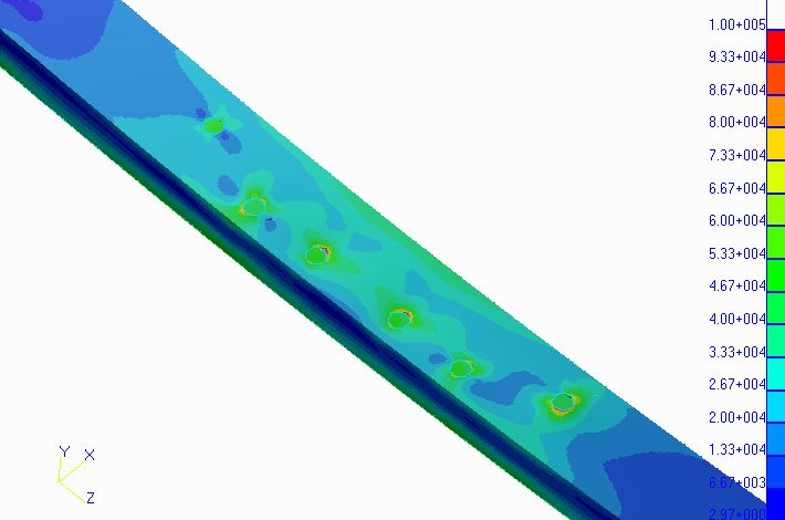
Here is the FEA of the Schertz beam.  Applied load is based on 6G's and the
beam assumed to pick up 2/3 of the 1800lb load, or 1200 lbs.  This is what
Bill used in his spreadsheet.  The load was distributed over the footprint
of the block.  I did not apply the "gyroscopic kick load" from the prop -
that would be a different load case.  For that case, if the brackets that
Chrissi mentioned are excluded, there is a potential for the oil pan bolt
loads to go up dramatically because of the heel-toe reaction of the block
against the beam.  This depends on the load path - how much load the rear
engine support picks up vs the beam.

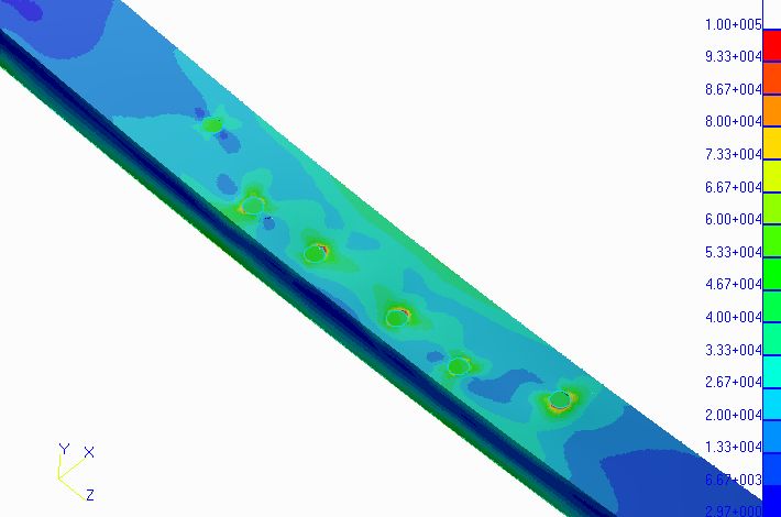
I tied the oil pan bolt holes rigidly together in Z to simulate being bolted
to the block - I could have tied them in X and Y as well but the results
will be similar.  I had to estimate the pan bolt spacing.  I assumed the
holes go completely through the beam for access.

For the beam, looks like max gross stress away from the holes is about 40ksi
vonMises.  Near the holes the stress is of course higher but the stresses
here would be spread out a bit because of the area of the fastener heads and
also fastener head friction from beam to block.   So, if you use a factor of
safety of 1.6 yield and 2.0 ultimate it seems OK.  Per Mil-HDBK-5, 4130
normalized.tempered, stress relieved is good for 75ksi yield/95ksi ultimate.
BTW, the model values are vary favorable with the hand calcs Bill did.  His
hand calcs show higher stress because of the applied concentrated center
load - the loads are distributed in the model.

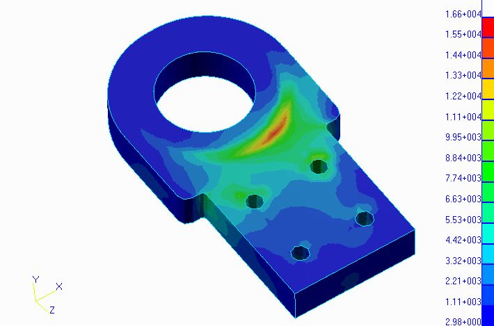
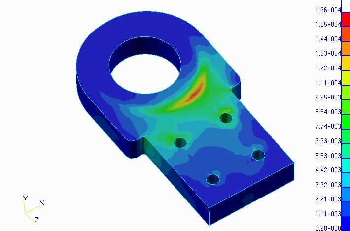
For the aluminum tabs, the stress levels seem acceptabe.  Max stress appears
to be about 16ksi.  MIL-HDBK-5, Ftu=42ksi and Fty=38ksi for 6061-T651 plate.
Positive margin of safety with FS of 1.6 yield/2.0 ultimate if the 6G load
is conservative.

Dan
The AirCraft Rotary Engine NewsLetter.  Powered by Linux.
ACRE NL web site. http://home.earthlink.net/~rotaryeng/
Copyright 1998-2003 All world wide rights reserved.