Ok, primary tubes (vice loop) will be shorter. Yes, with OAT around 70
and
higher my static is 5200-5300 rpm.  As the OAT drops the rpm goes up.
Around 50 deg I can get 5400-5500 and around 40F I can get 5800 rpm
static
runup. Yes, I've checked the prop with a digitial prop tach and the
numbers
are correct.  So it appears that my longer tubes (about 2" longer than
Tracy's) for a total 1/2 length of 21" moves my peak torque point down
the
rpm curve at bit.

I wish it were true indication of power, but it appears on a cold
morning I
get just enough more power to put the prop into a stall condition (which
of
course then takes less power to spin it even faster and that enable the
engine to produce a bit more HP which spins it faster - well, up to
about
5800-5900 rpm. Then apparently even the drag of the stalled prop
matches
the HP being produced.

My airstrip is 2300 ft long with trees and electric wires off one end
and
trees and golf course off the other, ponds on both sides of its 35 foot
width (a couple of folks have scared the ducks and geese in it).  Some
folks
refuse to land on it, but once you get use to it, its not bad.

Oh, by the way, that brazing rod did an excellent job of putting
additional
material on the edge where I had the hole break-out, I'll send a photo.

Ed
OK Ed thanks. So you are using a dynamic chamber. Is that correct?
With a total length of 42 inches? I would love to see a dyno curve on your
engine.
You have really good street porting as I recall. You should try 17 inches
with a simple plenum chamber and you should be able to give
Tracy a nice headwind. You don't really need all the torque at 1500 RPM.

Paul Lamar
Yes, after seeing your Sony Mavicas, I had to have one.  Excellent for this
sort of thing.
Regarding dynamic chamber, its more like a direct connection between the two
rotor's secondary ports and between their primary ports with no chamber in
between.  I calculated the pulse travel time at various rpms in order to
arrive at the length of the tubes to support the dynamic charging effect.
Had to make some assumptions about timing and port opening and closings as
well as the effects of different manifold pressure/density on speed of pulse
(basically the speed of sound)  While the length obviously changes with the
rpm, my calculations indicated 25" for 5000 and 21" for 6000 rpm (distance
from port on housing to throttle body).  My engine performance would appear
to indicate that my 21" distance gives me a boost in the mid 5000 range, so
shorter would indeed move it up the rpm band.

However, because my aircraft is a bit on the heavy side and I fly in and out
of grass strips, I prefer to have the additional power (if any) provided by
the dynamic charging effect for the take-off regime. I will shorten the
length this time to bring it down to 19" from 21" as clearly spinning a
stall prop is now doing me much good on take off {:>)    By the way, that is
total length from port to throttle body, the actually tube length is more
like  9" the remainder in the lower manifold and the throttle body housing.

By the way, pulled the manifold tubes out of the oven this morning after 8
hours of cooking and indeed they do appear to have hardened.  The tubes have
a distinct sheen rather than a dull color and they respond to a tap on the
tubes with a ring rather than a dull thud.  FWIW

Ed
Sounds like a dynamic chamber. If so it sounds like it is tuned for 2000-3000 RPM.

A simple tuned manifold with all four runners going into a 160 cubic inch plenum would be
about 17 inches from plenum to port at 6000 RPM and 21 inches at 5000 RPM. That
will also give good BSFC and torque at 5000 RPM.

A true dynamic chamber operating at its best
at 5000 RPM would be half that length or around 10-11 inches chamber to port.

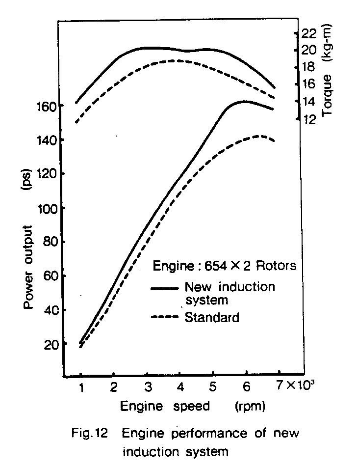
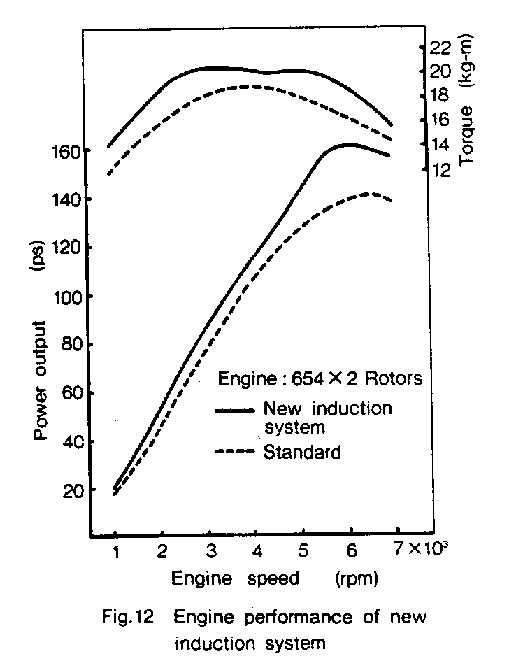
Here is a torque & HP curve on a stock dynamic chamber with runner lengths around
21 inches chamber to port. My guess on the exact length although I don't have
one here to measure. Note the torque hump at 2000-3000 RPM indicating the
dynamic chamber is working at the 2000-3000 RPM range. I have other charts
that correlate best torque with best BSFC. Same for a piston engine.

Tracy had this torque & HP curve in his book for some strange reason.
This gave the false impression that it was the thing to have on
your aircraft engine. Apparently he missed the significance of
the hump in the torque curve at 2000-3000 RPM. I am also to partially
to blame as it took me years to figure it out as I was confused by
Mazda SAE papers on the subject.

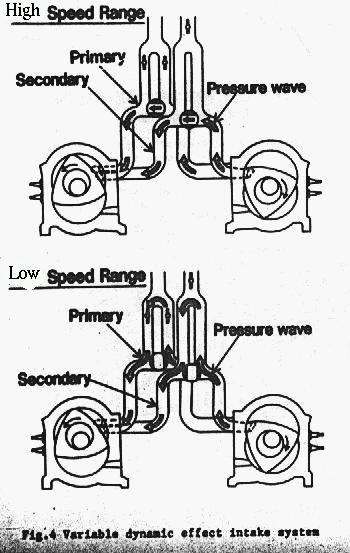
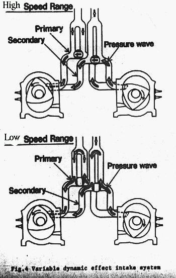
Here is an illustration out of a Mazda SAE paper on
the subject of series dynamic chambers probably used
on the RX8 engine. This had me confused for years as the diagram was mis
labeled in the SAE paper. Then one day it dawned on me the illustration
was mis-labeled. I fixed it in this version of the illustration
using Linux Paint.

Paul Lamar

The AirCraft Rotary Engine NewsLetter.  Powered by Linux.
ACRE NL web site. http://home.earthlink.net/~rotaryeng/
Copyright 1998-2003 All world wide rights reserved.