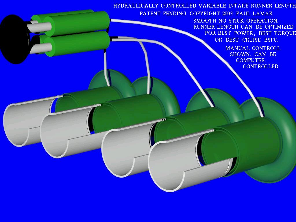
You don't have to pump the handle. The runner displacement
is 6.28 x .1 x the length of travel of the runner.
Or 3.14 cubic inches for a five inch travel.
Total displacement required for all four is 12.56 cubic inches.

With a knob that sticks out of the panel four inches
the area of the control cylinder is then 3.14 or
a radius of one inch. Check my arithmetic.

The control cylinder can be lightly constructed out of thin
wall 2 inch tubing as the pressure is minimal.

It is not like we are lifting the whole airplane.
Each runner gets 25% of the force applied to the knob.
If you apply 20 pounds to the knob the runners would see
5 pounds of moving force each. Way more than enough
and the pressure in the system would be 20/3.14 or
ONLY 7 PSI!!!!

Think of it as a low cost controllable
pitch prop. In for low pitch out for high pitch.

Paul Lamar
I discovered a minor design bug in the above arrangement. If one runners sticks
the others will take up the volume of fluid and extend or contract
more than the sticking runners. Therefor what is needed is four individual
control cylinders. Two of which are smaller for the center runners.
Each roughly one inch in diameter. Four cylinder holes could be bored
in a 2 by 2 block of aluminum or four individual cylinders could
be fastened together as shown.

I used Bill Jepson's idea for the step down but on hind site it leads
to a larger plenum chamber. This is much simpler than the RX8 intake system.
It is also always  optimized, when automated, for all possible conditions
of power, fuel consumption and RPM. One of the reasons Mazda won
Lemans using a similar intake system when they had a fuel quantity limit.

Unfortunately it will also work well on a piston engine :)

Paul Lamar


The AirCraft Rotary Engine NewsLetter.  Powered by Linux.
ACRE NL web site. http://home.earthlink.net/~rotaryeng/
Copyright 1998-2003 All world wide rights reserved.