You don't have to pump the handle. The runner displacement
is 6.28 x .1 x the length of travel of the runner.
Or 3.14 cubic inches for a five inch travel.
Total displacement required for all four is 12.56 cubic inches.

With a knob that sticks out of the panel four inches
the area of the control cylinder is then 3.14 or
a radius of one inch. Check my arithmetic.

The control cylinder can be lightly constructed out of thin
wall 2 inch tubing as the pressure is minimal.

It is not like we are lifting the whole airplane.
Each runner gets 25% of the force applied to the knob.
If you apply 20 pounds to the knob the runners would see
5 pounds of moving force each. Way more than enough
and the pressure in the system would be 20/3.14 or
ONLY 7 PSI!!!!

Think of it as a low cost controllable
pitch prop. In for low pitch out for high pitch.

Paul Lamar
I discovered a minor design bug in the above arrangement. If one
runners
sticks
the others will take up the volume of fluid and extend or contract
more than the sticking runners. Therefor what is needed is four
individual
control cylinders. Two of which are smaller for the center runners.
Each roughly one inch in diameter. Four cylinder holes could be bored
in a 2 by 2 block of aluminum or four individual cylinders could
be fastened together as shown.

I used Bill Jepson's idea for the step down but on hind site it leads
to a larger plenum chamber. This is much simpler than the RX8 intake
system.
It is also always optimized, when automated, for all possible
conditions
of power, fuel consumption and RPM. One of the reasons Mazda won
Lemans using a similar intake system when they had a fuel quantity
limit.
Unfortunately it will also work well on a piston engine :)

Paul Lamar
I reversed it again to make the cylinders stationary and added four walls
of the plenum chamber and a throttle body for concept clarity. We don't need
much plenum room as our RPM range is much more narrow than that required
by a car. This 3D does not show the total room needed. Depends
somewhat on the max RPM of the engine used and the PSRU gear ratio.

Here too is diagram of the RX8 series dynamic chambers for
comparison.

Paul Lamar
Dan Ruggirello wrote:
That is a beeeutiful rendering Paul.  Maybe Rhino isn't all that bad ;-)
Not sure if you already addressed the  - high vacuum
load on the hydralic cylinder design?

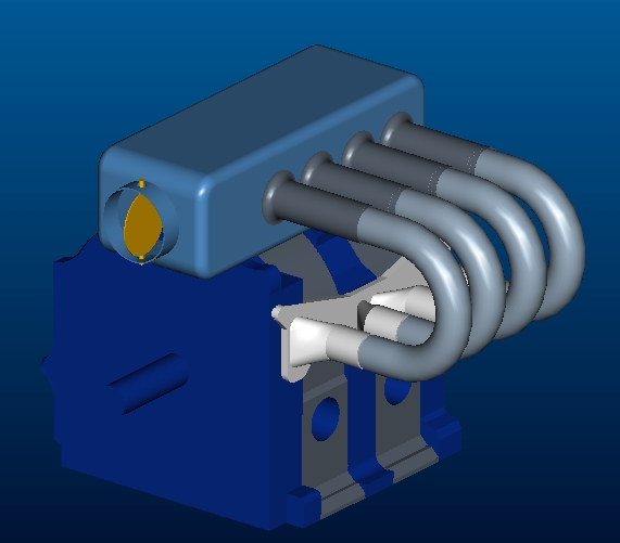
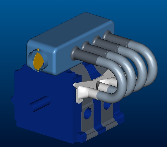
Here is a conceptual trombone intake system.  Here, the bellmouths are
stationary WRT the plenum.  Maybe I would incorporate the hydraulic idea to
operate the 180 degree bends.  I suppose one would need adaquate clearance
between engine and cowling.

Dan
Well sudden throttle closure is something worry about. It would increase
the pressure on the O-rings to 15 psi from 7 psi but they should be able to take it.
If the runners move the control knob would pop out of the instrument
panel but no further than the stops.

Your trombone shows much promise for the car application as the RPM range
is 2000 to 8000 and space is an issue. Might be a good idea to put
a bit of rubber hose in there here and there  to ease the alignment issues.

Paul Lamar

The AirCraft Rotary Engine NewsLetter.  Powered by Linux.
ACRE NL web site. http://home.earthlink.net/~rotaryeng/
Copyright 1998-2003 All world wide rights reserved.