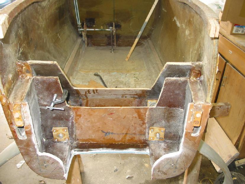
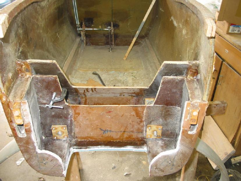
OK I will draw it into the 3D.
Perry mentioned your engine looked a bit too far aft. How far
is it
>from the e-shaft pulley to the firewall.
Paul Lamar
Joseph Berki wrote:
Paul,
         It is 27" from the firewall to the bellhousing location
where the
ears are bolted. Used this location because the widest point of
the mount
is further forward than plate design making it easier to
cowl. Have you
tested the wedge duct / diffuser? I thought the Caravan episode
was a K&W
duct?  Thanks
Joe
No the Caravan test was a simple wedged shaped duct. The K&W duct has
a few
problems for our use. Number one is; it is only valid for rads mounted
perpendicular to the axis of the duct. This means any tilting
of the rad becomes highly configuration sensitive and extensive
development would be required to insure uniform air flow through
the core. You could spend months with a test rig optimizing the
exact shape of the duct. Velocity taps should be used all
over the back side of the rad to insure uniform air flow.
The second major problem is the K&W is too long. In your case
it would be half the length of the fuse :)

BTW Those are real big problems with rads mounted on either
side of the PSRU in a tractor configuration. Thick or thin they
both have the same problems. Nobody is doing their homework on this.

Paul Lamar
Joseph M Berki wrote:
Paul,
         I will look and see if the wedge inlet is doable.  I will get
those dimensions for you also.  If I tilt the tray horizontal and
the wedge
shape/scoop hangs down what is the dimension of the back side
diffuser?  What does the wedge inlet look like from the front/back?
I don't understand the first question.
Inlet area is 25% to 30% of the core area.
Can the scoop opening be smaller than the width of the radiator?
Yes but the inlet duct cross sections should be constant area up to where
the wedge starts.
Does it need a large area/volume like the K&W?
No. One of the wedges advantages.
That is one of the reasons I tilted it so
a plenum could be built on the back side of the firewall occupying the
space between the firewall and engine.  I have some ideas for the
augmenter
(incorporate the muffler into the augmenter) but there are som NACA
reports
I would like to look at but I think they will not be of much help.

Joe
Joseph Berki wrote:
Paul,
         The distance between the fuselage floor and the bottom of the spar
at the aft landing gear bulkhead is 12.75" , at the firewall it is
11.5".  I looked at the possibility of laying the radiator down parallel to
the fuselage floor and let the wedge hang down into the air stream.  The
limiting factors were the lower motor mount hard points Clearance for an
opening for cooling could be 16" max.   The biggest radiator would be 10" X
24" which would mean it would have to be 3" thick.  I found a NACA paper on
rectangular augmenters which would fit with the wedge in that everything
could be rectangular but I don't think it would exit the air frame
correctly.
Joe
A sixteen inch wide opening would be OK but it must be about 4 or 5 inches
deep.

Does the structure look like this Long Ez? That does not give you
much room under the landing gear for an inlet duct. Do you want to
locate the inlet duct up and over the landing gear beam?

I think the biggest problem with this idea is the loss of
structural strength in the fuselage and the landing gear if you move
the inlet and inlet duct forward and above the landing gear.

BTW If I decided to design a canard airplane I would fasten the
landing gear to the spar anyway. Burt made a few structural
mistakes here and there. Particularly those silly aluminum angle
motor mount stringers only ten inches apart. Might be OK for
a Volkswagen engine. I digress.

Getting the back of the rad clear from obstructions is the next problem.

How far is the engine from the firewall?

If the air is flowing through the rad properly a 500 cubic inch core
should work fine. That means only 2 inches thick. A 3 inch core would
give a volume of 720 cubic inches. The back half of the 3" thickness
would be doing only 1/4 of the work so assuming you could get the air to
flow through the 3" core it would be much less efficient and only cool
a little bit better.

Why not move the augmentor aft under the psru?
That would give plenty of room under the engine for the rad.

Do you have a sketch of what you have in mind for the augmentor?

Paul Lamar
Joseph M Berki wrote:
Paul,
         It is 10 3/8" from the Eshaft front bolt head to the firewall.  My
EZ is not like a long but mounts the main gear between two bulkheads that
meet the main spar.  The aft LG bulkhead meets it at the front while the
forward LG bulkhead goes up about 4 to 5" and is tilted back and meets the
spar about 1" up the front lower edge of the spar.  This transmits the LG
loads to the spar. The Cozy MkIV is like this and Rutan did this in the
Defiant. I can make a 16" wide opening that will start at the aft LG
bulkhead and end at the firewall this permits movement of the rad/oil
cooler to this point.  Here there is 12.75" from the fuselage floor to the
spar bottom. The 12 X 24 radiator is now 10 X 24 if I use a 16"
opening.  Farther up in the "hell hole" it is 18".  There is no need to go
above the gear.  The augmenter will move back.  It is a tube within a tube
with air flowing around the outer tube and through the inner one.  The
space between the tubes is divided into two sections and is fed from each
rotor.  The exhaust travels around this space, not unlike the tangential
muffler, and is discharged into the inner tube at an angle facing
rearward.  I have no idea if this would work but it looked like a solution.
OK I got it!! This picture did it for me.

Do away with those silly box sections and sections of the
fuselage  that mount the lower motor mount tubes. Make steel  brackets that
picks up the landing gear bolts and fasten the tubes directly directly to the landing
gear bolts. That is where the high G engine loads ultimately go anyway.
That will allow a wider and shorter rad, giving more room above the
rad for clearance and solve a whole lot of pusher cooling problems
not to mention doing away with some heavy redundant structure.
Mount the rad horizontal like before. this should work on every pusher
ever built. You can add a structural bulkhead from the bottom aft
edge of the spar forward to just above the landing gear bolts if you wish.

I'll do a 3D.

Paul Lamar

The AirCraft Rotary Engine NewsLetter.  Powered by Linux.
ACRE NL web site. http://home.earthlink.net/~rotaryeng/
Copyright 1998-2003 All world wide rights reserved.